 |
 06-16-2023, 06:07 AM
|
#1
|
|
Winnebago Owner
Join Date: May 2018
Location: Houston, Texas
Posts: 38
|
Transfer Switch wiring 2000 Adventurer 32
I have just installed a new ATS (automatic transfer switch) in my 2000 Adventurer, 32 ft., Ford chassis. Winnebago's wiring is shown below. I don't know what to do with the two connections that are circled in yellow. There are instructions shown at the bottom, but they don't help me. I put the two white leads in with the other white ones and everything seems to be working, but I really would like to know what the diagram would have me do.
Anyone know about this?
Thanks.
__________________
Chuckmor
2000 Winnebago Adventurer, 32
Houston, Texas
|

|

|
|
06-16-2023, 07:42 AM
|
#2
|
|
Winnebago Master
Join Date: Nov 2018
Location: Pflugerville/Austin, Tx
Posts: 7,537
|
Sorry but that is not one I've seen before and it does leave questions!
Is this a drawing for a new/updated transfer switch that you are using to replace a different model?
It doesn't match the "normal" drawings we get online, so where does this drawing come from? With new switch, maybe?
I might give Winnebago a call on this one as it seems to need better info. Noy going to work to just remove the white leads.
They need to go "somewhere" but they don't say where that I can spot.
Written like too many instructions. The guy that wrote them assumes "everybody" knows that !
Sorry, no good ideas here!
__________________
Richard
Why no RV year, make and floorplan on MY signature as we suggest for others?
I currently DO NOT have one! 
|
|
|
|
|
06-16-2023, 08:22 AM
|
#3
|
|
Site Team
Join Date: Sep 2009
Location: Spring Branch, TX
Posts: 7,836
|
I’m not sure what that Winnebago wiring diagram is meaning either, but looking at that diagram could those be capped off and not used? Perhaps to be used for some options not on all coaches?
Obviously these “5” and “6” instructions are clear as mud.
I don’t suppose you took a photo of the original wiring before the ATS replacement?
__________________
2017 Winnebago Adventurer 37F
2016 Lincoln MKX Toad
|
|
|
|
|
06-16-2023, 08:29 AM
|
#4
|
|
Site Team
Join Date: Sep 2009
Location: Spring Branch, TX
Posts: 7,836
|
Quote:
Originally Posted by Morich

It doesn't match the "normal" drawings we get online, so where does this drawing come from? With new switch, maybe?
|
Richard those are Winnebago wiring diagrams from a 2000 Adventurer 32V.
Heres a link
https://www.winnebago.com/Files/File...000/132290.pdf
__________________
2017 Winnebago Adventurer 37F
2016 Lincoln MKX Toad
|
|
|
|
|
06-16-2023, 08:35 AM
|
#5
|
|
Winnebago Master
Join Date: Dec 2003
Location: Motor City, Mich
Posts: 1,004
|
As I recall there are some jumper wires used for coaches with 50 amp service. I know I've seen details of the jumpers somewhere. Parallax transfer switch, right? Has to be a diagram out there somewhere....
__________________
Tim.
|
|
|
|
|
06-16-2023, 10:27 AM
|
#6
|
|
Winnebago Master
Join Date: Nov 2018
Location: Pflugerville/Austin, Tx
Posts: 7,537
|
Quote:
Originally Posted by creativepart
|
Okay, looked at a different drawing for the 110AC and did not come this far. It looks like they are dealing with an Rv with option 12D? That makes it a 30 Amp, but where those wires that look like they are just going behind the connections really land is not clear to me?
Part of the problem may be the way they tend to confuse things by using different names at different places. I "think" note 6 makes some sense but then when they went to note 5, I'm guessing they swapped in "panel" for where they labeled the drawing "load center" just to confuse things.
I'm thinking the "panel" is what they labeled "load center" and the wires they mention should just be removed, not necessarily attached at a different point?
It looks like they have three sections to the switch. Red for load conter/panel, depending on which label you use? Blue for power cord section and green for generator section.
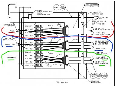
But that is doing some guessing and taking things for granted which may not always be true? Can we assume that thisis the correct drawing and the correct options?
If true, are there blue marked wires as the note mentions? Since there is no word to connect them, I might be inclined to leave them capped but that might need to be compared to the OEM wiring as there is a fair amount of doubt involved.
If it is OEM to OEM swap, I would go back with what methods were used at start!
__________________
Richard
Why no RV year, make and floorplan on MY signature as we suggest for others?
I currently DO NOT have one!
|
|
|
|
|
06-16-2023, 11:34 AM
|
#7
|
|
Winnebago Owner
Join Date: May 2018
Location: Houston, Texas
Posts: 38
|
Thanks guys.
I'm embarrassed to say that the original transfer switch was destroyed when I drove off trailing my power cord. probably ran over it with rear tire. Strange I didn't feel it.
Anyway it was a 50 amp transfer switch, so I replaced it with a
Esco LPT50BRD LYGHT 50 Amp ATS. Wiring was straightforward except for the items in question. I did note that one of the white wires still in the coach still had a wire nut on it, as shown in the diagram.
I inserted the two white wires that are shown to go with 'blue' wires into the neutral lug with the other white from the corresponding cable (hope that made sense).
As I said, every thing seems to be working except that I'm suspicious of my basement a/c. I'm waiting for new breakers for the genset before I get serious about checking that out.
__________________
Chuckmor
2000 Winnebago Adventurer, 32
Houston, Texas
|
|
|
|
|
06-16-2023, 11:57 AM
|
#8
|
|
Winnebago Master
Join Date: Nov 2018
Location: Pflugerville/Austin, Tx
Posts: 7,537
|
Okay, that can throw things into a bit more confusion as the drawing that we have been referring to is for 30AMP!
So we may need to start from the bottom with questions and work up?
Is your RV 30 or 50 amp? They were both build for that year, model, and floor plan. I have to go with the idea that they may have gone with the same transfer switch for both but it pays to check?
If unsure, a look at the power cord will show if it is a heavier 6-3 cord or lighter weight 10-2?
Point is to make sure we are looking at the correct info.
Not that it will make the drawing any more clear but a place to start!! 
Note?
Don't feel bad about those little "adventures". I once backed over a concrete and steel grill while three people were outside to watch me back in!!
We do those things so we have stories to tell on other people! 
__________________
Richard
Why no RV year, make and floorplan on MY signature as we suggest for others?
I currently DO NOT have one!
|
|
|
|
|
06-16-2023, 12:01 PM
|
#9
|
|
Winnebago Owner
Join Date: May 2018
Location: Houston, Texas
Posts: 38
|
Sorry, I meant to state originally that the coach is 30 amp. Original ATS was 50 amp, so that's what I went back with.
__________________
Chuckmor
2000 Winnebago Adventurer, 32
Houston, Texas
|
|
|
|
|
06-16-2023, 04:26 PM
|
#10
|
|
Winnebago Master
Join Date: Nov 2018
Location: Pflugerville/Austin, Tx
Posts: 7,537
|
No problem! I screw up the communications so often, I'm getting paranoid on checking details!
I'm still not seeing a real good answer to what yu are asking but I did a second look at where I had first checked for the 110AC drawings and it does show things in a bit different way, that I am more used to looking at, so maybe I can send some ideas along on what BOTH drawings seem to show and maybe one or the other can lead to some light?
winnebago uses tow different drawing types to get info across to us. One is the wiring diagram while the other is an installation drawing. The first gives it more wire by wire and the second that we have mostly been speaking about is lots more help on the physical layout and where things are installed.
So I started off on the wire diagram, while you had the install, but they both have matching info, shown in different ways!
I took the first drawing and turned it to match what I find on the other drawing, to try to compare what they both are saying.
I can sort out the three sections on each as green, red and blue but there is a problem which I'm not sure what it says about one wire on the blue group.
The one with the question mark? I'm not happy with whether that is sending power to or from the load center/ panel!
My basic idea of the transfer switch is that it chooses either green or blue section and sends the power out to the load center on red!!
This comes from this drawing set:
https://www.winnebago.com/Files/File...000/131759.pdf
Click these snips to get a better picture!
Sending it along to look over but I'm not seeing a clear answer for what to do with the wires they say to disconnect???? More looking and study leaves me more confused than starting! 
__________________
Richard
Why no RV year, make and floorplan on MY signature as we suggest for others?
I currently DO NOT have one!
|
|
|
|
|
06-16-2023, 04:55 PM
|
#11
|
|
Winnebago Owner
Join Date: May 2018
Location: Houston, Texas
Posts: 38
|
Richard,
I really appreciate your diligence in pursuing my problem. The clips you sent definitely deserve further study, but it may be a day or so before I can devote sufficient time to it. Tomorrow I'll be replacing a hydraulic cylinder on my slide-out. Not a fun job.
Thanks.
Later.
Chuck
__________________
Chuckmor
2000 Winnebago Adventurer, 32
Houston, Texas
|
|
|
|
|
06-18-2023, 04:22 PM
|
#12
|
|
Winnebago Owner
Join Date: May 2018
Location: Houston, Texas
Posts: 38
|
Yesterday was too hot for an old guy to be out working on the RV. Anyway I've looked over your information and still have no clue about the two connections in question.
I wired them into the neutral lugs with the other white wire of the pair coming in. Every thing seems to be working, but I want to check the basement A/C operation to make sure that is working right.
I'm going to sell the old girl (the RV) and I'm doing (done) a lot of fix-up. It's been a great ride. 63,000 miles in all of the lower 48 states.
__________________
Chuckmor
2000 Winnebago Adventurer, 32
Houston, Texas
|
|
|
|
|
06-22-2023, 01:59 PM
|
#13
|
|
Winnebago Master
Join Date: Jun 2013
Location: Full-timer/volunteer w/SOWERS
Posts: 2,737
|
Quote:
Originally Posted by Chuckmor
I have just installed a new ATS (automatic transfer switch) in my 2000 Adventurer, 32 ft., Ford chassis. Winnebago's wiring is shown below. I don't know what to do with the two connections that are circled in yellow. There are instructions shown at the bottom, but they don't help me. I put the two white leads in with the other white ones and everything seems to be working, but I really would like to know what the diagram would have me do.
Anyone know about this?
Thanks.
|
As I look at this I do have some questions for you. Is your shore cord 50A or 30A? Where did you get this wiring picture of the ATS? If I read your picture correctly it shows a 12AWG, 2 wire power cord and 10AWG generator feed. I'm not certain form the information you are providing that this ATS is the correct size for your coach.
In this .pdf from the Winnebago resource center ( https://www.winnebago.com/Files/File...000/131759.pdf) you have 2 ATS choices; 50A or 30A.
So, before I can give you any valid input I need these questions answered.
I'm so glad that you have come to the community for help with this project. I know one of us will get you the correct information. I am among the many here who have replaced ATS's and have a bit of an understanding about reading the older Winnebago diagrams. The rigs after 2005 don't have as much detailed information available from Winnebago. So sad. These functional diagrams as so useful.
Rick 
__________________
Rick & Melissa Young & Dawson (RIP), 2011 Meridian 40U, FL XCL, ISL 380HP/DEF, Al 3000 MH, 2014 Honda CR-V, SMI AF1, Blue Ox TruCenter & tow equip.,EEZTire TPMS.
Servants On Wheels Ever Ready. Best job we ever paid to do  . (full time volunteers) . (full time volunteers)
|
|
|
|
|
06-22-2023, 05:12 PM
|
#14
|
|
Winnebago Owner
Join Date: May 2018
Location: Houston, Texas
Posts: 38
|
My coach is 30 amp with a 30 amp power cord. The Previous ATS was 50 amp, so that's what I went back with. Diagrams are all from Winnebago
https://www.winnebago.com/Files/File...000/132290.pdf
__________________
Chuckmor
2000 Winnebago Adventurer, 32
Houston, Texas
|
|
|
|
|
06-23-2023, 04:48 PM
|
#15
|
|
Winnebago Master
Join Date: Jun 2013
Location: Full-timer/volunteer w/SOWERS
Posts: 2,737
|
Quote:
Originally Posted by Chuckmor
|
My apology. I didn't scroll down far enough in that .pdf. So, you have A/C #2 wired through the ATS. In https://www.winnebago.com/Files/File...000/131759.pdf sheet 1 of 4 you may find a clue to your question. Does your 30A ATS have a "blue wire"? Looking at Sheet 1, ATS "Panel" connections you can see a Neutral, Hot and Gnd terminals. The "Connector" you have circled is a wire nut I am thinking. I have no idea where the White wires are going from the connectors. Are there 2 white wires coming up from under the terminal strip? Do you have a box near the ATS that the power cord goes into and has a 30A breaker?
Another thought is "Panel" is a reference to the neutral coming from the load center and tied to A/C # 2 neutral. Same with the "Power Cord". This is the neutral feed to the load center tied in at the ATS with a wire nut.
Hope this all helps you make some sense of this.
Rick
__________________
Rick & Melissa Young & Dawson (RIP), 2011 Meridian 40U, FL XCL, ISL 380HP/DEF, Al 3000 MH, 2014 Honda CR-V, SMI AF1, Blue Ox TruCenter & tow equip.,EEZTire TPMS.
Servants On Wheels Ever Ready. Best job we ever paid to do . (full time volunteers)
|
|
|
|
|
|
Currently Active Users Viewing This Thread: 1 (0 members and 1 guests)
|
|
|
 Posting Rules
|
You may not post new threads
You may not post replies
You may not post attachments
You may not edit your posts
HTML code is Off
|
|
|
|
 » Recent Discussions
 |
|
|
|
|
|
|
|
|
|
|
|
|
|
|
|
|
|
|
|
|
|
|
|
|
|


 Linear Mode

