 |
|
 09-10-2023, 05:16 PM
|
#41
|
|
Winnie-Wise
Join Date: Mar 2022
Location: Wenatchee, WA
Posts: 332
|
Quote:
Originally Posted by dkoldman

It is over my pay grade. Why is the polarity reversed? I have to have Red probe on white wire to get 11.25vdc. Also, I just traced that same white wire to a connector on other side of connector it is yellow which normally for WBGO is hot.
|
Then try putting your red probe in the connector on the other side of that yellow wire, ground the black probe and see if you get a reading.
FYI - in my case, the wire running from the actual fuse panel to the Monitor panel is purple and white. I actually traced it out with a "tone circuit tracer" though I did not pull the monitor off the wall. In fact, the "Hot" wires coming from the fuse panel are all different colors, none are solid yellow.
I want to clarify, your LED is inside your switch and lights up the switch when it is turned on, correct. If not and it is separate from the switch, ignore everything I have said as I am bowing out.
__________________
Bob & Shelly - 2022 Minnie 2529RG TT, 400AH LiFePo4 380W Solar
2016 RAM 3500 CC SRW SB Cummins
Remember, no matter where you go, there you are.
|

|

|
|
09-10-2023, 06:16 PM
|
#42
|
|
Winnebago Master
Join Date: Jun 2020
Location: Dallas, Texas
Posts: 1,051
|
Quote:
Originally Posted by No1Hunter
Then try putting your red probe in the connector on the other side of that yellow wire, ground the black probe and see if you get a reading.
FYI - in my case, the wire running from the actual fuse panel to the Monitor panel is purple and white. I actually traced it out with a "tone circuit tracer" though I did not pull the monitor off the wall. In fact, the "Hot" wires coming from the fuse panel are all different colors, none are solid yellow.
I want to clarify, your LED is inside your switch and lights up the switch when it is turned on, correct. If not and it is separate from the switch, ignore everything I have said as I am bowing out. It is not, it is separate, see picture in post #17 although it is sideways
|
The LED is not inside OEM switch, it is separate; see picture in post #17 although it is sideways. My hope is that the new switch can have the integrated LED because I will have to cut a small square hole in the wall to mount just above or below a light switch in bath room.
I now have confirmation that all 3 of the wires on OEM switch is for the Water Pump. The white wire called T9 on schematic is for the bottom contact #3 on the switch. In the connector T9 is fed by a yellow wire. That yellow wire has to be hot, but thus far I have not been able to get the exact wire code for all 3 of those wires coming from WBGO harness.
The ground for the separate LED for the water pump is jumpered to same ground on the water heater LED, that ground goes through the connector T3 and is the only white wire coming from WBGO harness to the 15pin connector.
The more I dig, the confusing it gets because it seems like the switch has two incoming sources of 12v+ when matched to white wire 3# on pin. It is also strange that when voltage goes to zero, the LED and pump comes on 
lrv3 says he need some time so I can patiently wait. Right now, I just want to know, I still have my 52oz water bottle as backup 
__________________
2019 Sunstar 29ve; Toad Lincoln Navigator; RVi Brake 3; Roadmaster Nighthawk 676; Sumo Springs; Safe T Plus; Onan EC-30 AGS; Vmax 250ah AGM; T-Mobile Internet; Southwire EMS 44270/34951 Display 40301; Jet Flo Macerator; Alpine SPE500 Speakers; Visio M21D-H8R
|
|
|
|
|
09-10-2023, 06:22 PM
|
#43
|
|
Winnie-Wise
Join Date: Mar 2022
Location: Wenatchee, WA
Posts: 332
|
Quote:
|
A switch with red LED that allows me to turn on the Main Water Pump while in the Bathroom.
|
My bad. I took this to mean the switch lite up via a red LED. All my switches are lighted and, thus, completely different from what you have. I am afraid I won't be much help and as I stated previously, I am bowing out of this discussion.
__________________
Bob & Shelly - 2022 Minnie 2529RG TT, 400AH LiFePo4 380W Solar
2016 RAM 3500 CC SRW SB Cummins
Remember, no matter where you go, there you are.
|
|
|
|
|
09-10-2023, 06:53 PM
|
#44
|
|
Winnebago Master
Join Date: Jun 2020
Location: Dallas, Texas
Posts: 1,051
|
Quote:
Originally Posted by No1Hunter
My bad. I took this to mean the switch lite up via a red LED. All my switches are lighted and, thus, completely different from what you have. I am afraid I won't be much help and as I stated previously, I am bowing out of this discussion.
|
 Just so you know, it did mean exactly what it said and what you took it to mean. But it states the switch in the bathroom, one that I do not have right now and is the subject of what I wish to install for this thread.
The switch I used for reference is https://www.amazon.com/gp/product/B0...KIKX0DER&psc=1 It sounds like what you have or similar.
My OEM switch has a separate LED as does my water heater and all of the other level indicators on the WBGO OEM Control Panel.
__________________
2019 Sunstar 29ve; Toad Lincoln Navigator; RVi Brake 3; Roadmaster Nighthawk 676; Sumo Springs; Safe T Plus; Onan EC-30 AGS; Vmax 250ah AGM; T-Mobile Internet; Southwire EMS 44270/34951 Display 40301; Jet Flo Macerator; Alpine SPE500 Speakers; Visio M21D-H8R
|
|
|
|
|
09-11-2023, 06:11 AM
|
#45
|
|
Winnebago Master
Join Date: Jun 2020
Location: Dallas, Texas
Posts: 1,051
|
I have found a new switch that I would prefer to use if this can be figured out. It is actually labeled water pump
https://www.ebay.com/itm/35344783563...Cclp%3A4429486
__________________
2019 Sunstar 29ve; Toad Lincoln Navigator; RVi Brake 3; Roadmaster Nighthawk 676; Sumo Springs; Safe T Plus; Onan EC-30 AGS; Vmax 250ah AGM; T-Mobile Internet; Southwire EMS 44270/34951 Display 40301; Jet Flo Macerator; Alpine SPE500 Speakers; Visio M21D-H8R
|
|
|
|
|
09-11-2023, 08:10 AM
|
#46
|
|
Winnebago Master
Join Date: Nov 2018
Location: Pflugerville/Austin, Tx
Posts: 7,543
|
Not moving the idea forward but I might be able to explain what I think you are seeing when you say this?
"The more I dig, the confusing it gets because it seems like the switch has two incoming sources of 12v+ when matched to white wire 3# on pin. It is also strange that when voltage goes to zero, the LED and pump comes on"
We tend to think of voltage as a thing we can find of take out and see but the definition of voltage is a DIFFERENCE" in potetnial.
Potential might be called an ability to do work?
When we check voltage we often test from a spot to ground and ground is the "normal" reference point. Positive post to ground is 12Volts?
It's not a solid thing but the difference between the positive post and ground!
When we read from the left side of the switch here with the switch open and the other probe on 1 or 2, we get a difference of 12 volts to the ground, either direct to the frame ground or through the pump.
But if we move that second probe up to 1, we get 12volt difference UNTIL we close the switch. When the switch is closed the meter says the voltage went away because it is reading the difference between th eleft side and 1 but they are now connected together and there is no difference, so the meter says zero as if the voltage is gone.
The power still flows through both points where the meter is connected and the motor runs but the meter sees no difference!
A second thing that might be throwing confusion is beginning to look more likely. If this switch is designed as one to use where we have more than one point to turn the pump on/off, this may be a third wire called a "traveler" like we might have at staris in a house.
It may be that they have set the RV wiring up with wiring that has potential for an optional switch that you may not have??
Like we thought you had two switches already? If you only have one, there may be a wire set hanging somewhere that you don't know about and it is all ready to add a switch ???? 
All this confusion becasue they did not post up a full schematic of what they built for us to mod!
If you dig down to the Winnebago wire ID, there are 20 different wires listed in the ID chart for different wires for different numbers of switches.
I think we will find JA and JP are battery and ground to the monitor panel for everything on that panel.
Then AF and AG are wires that are some way related to the water pump and switch at the monitor panel.
But that is pretty close to guessing without really firm info!
__________________
Richard
Why no RV year, make and floorplan on MY signature as we suggest for others?
I currently DO NOT have one! 
|

|
|
|
09-11-2023, 12:39 PM
|
#47
|
|
Winnebago Master
Join Date: Jun 2020
Location: Dallas, Texas
Posts: 1,051
|
Quote:
Originally Posted by Morich
Not moving the idea forward but I might be able to explain what I think you are seeing when you say this?
"The more I dig, the confusing it gets because it seems like the switch has two incoming sources of 12v+ when matched to white wire 3# on pin. It is also strange that when voltage goes to zero, the LED and pump comes on"
We tend to think of voltage as a thing we can find of take out and see but the definition of voltage is a DIFFERENCE" in potetnial.
Potential might be called an ability to do work?
When we check voltage we often test from a spot to ground and ground is the "normal" reference point. Positive post to ground is 12Volts?
It's not a solid thing but the difference between the positive post and ground!
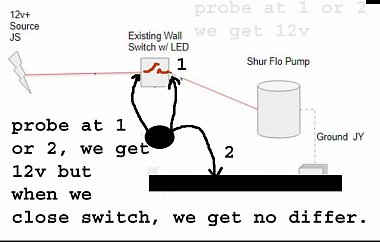
Attachment 187254
When we read from the left side of the switch here with the switch open and the other probe on 1 or 2, we get a difference of 12 volts to the ground, either direct to the frame ground or through the pump.
But if we move that second probe up to 1, we get 12volt difference UNTIL we close the switch. When the switch is closed the meter says the voltage went away because it is reading the difference between th eleft side and 1 but they are now connected together and there is no difference, so the meter says zero as if the voltage is gone.
The power still flows through both points where the meter is connected and the motor runs but the meter sees no difference!
A second thing that might be throwing confusion is beginning to look more likely. If this switch is designed as one to use where we have more than one point to turn the pump on/off, this may be a third wire called a "traveler" like we might have at staris in a house.
It may be that they have set the RV wiring up with wiring that has potential for an optional switch that you may not have??
Like we thought you had two switches already? If you only have one, there may be a wire set hanging somewhere that you don't know about and it is all ready to add a switch ????
All this confusion becasue they did not post up a full schematic of what they built for us to mod!
If you dig down to the Winnebago wire ID, there are 20 different wires listed in the ID chart for different wires for different numbers of switches.
I think we will find JA and JP are battery and ground to the monitor panel for everything on that panel.
Then AF and AG are wires that are some way related to the water pump and switch at the monitor panel.
But that is pretty close to guessing without really firm info! |
Morich, this is some really good stuff. Whether I get a 2nd switch or not, I am going to have sit down when I get home from work and more time to read and understand what you say about the potential voltage.
__________________
2019 Sunstar 29ve; Toad Lincoln Navigator; RVi Brake 3; Roadmaster Nighthawk 676; Sumo Springs; Safe T Plus; Onan EC-30 AGS; Vmax 250ah AGM; T-Mobile Internet; Southwire EMS 44270/34951 Display 40301; Jet Flo Macerator; Alpine SPE500 Speakers; Visio M21D-H8R
|
|
|
|
|
09-11-2023, 12:51 PM
|
#48
|
|
Winnebago Master
Join Date: Jun 2020
Location: Dallas, Texas
Posts: 1,051
|
New info that may be a breakthrough for the experts.
I was able to pull the 15 pin connector and it solves the mystery of why two 12v+ wires on Switch contact #1 (top of switch, red/white wire, & pin T7), and contact #2 (middle of switch, red wire & pin T8)
Pin 7 is NOT USED by WBGO
There is no pin connector in position T7
The two wires that are used from the switch are as follows
JA => Pin T9 Solid Red from switch and is the inbound 12v+ from the breaker
JS => Pin T8 White from the switch and is the outbound 12v+ to the water pump
__________________
2019 Sunstar 29ve; Toad Lincoln Navigator; RVi Brake 3; Roadmaster Nighthawk 676; Sumo Springs; Safe T Plus; Onan EC-30 AGS; Vmax 250ah AGM; T-Mobile Internet; Southwire EMS 44270/34951 Display 40301; Jet Flo Macerator; Alpine SPE500 Speakers; Visio M21D-H8R
|
|
|
|
|
09-11-2023, 01:08 PM
|
#49
|
|
Just Trying to Help
Join Date: Aug 2015
Posts: 526
|
dkoldman-
Nice job!
I would expect what you found. Pin 7 is used when there is a second switch. I've found an example on a different Winnebago coach. It will take me a while to put together the info I've dug out so far. That should give us a circuit diagram to add a second switch the "Winnebago way."
I also think we can find something to make the switch in the bathroom look OEM. It would help me if you could take a picture of the existing light switch.
It would help me also to have a clear photo of the side and ends of the 15-pin connector. There are at least a couple options on how to modify or add to that connector without splicing, making the second switch addition "plug and play."
__________________
Mark
2008 Holiday Rambler Admiral 30PDD (Ford F-53 chassis)
2009 Honda Fit Sport
|
|
|
|
|
09-11-2023, 02:17 PM
|
#50
|
|
Winnebago Master
Join Date: Nov 2018
Location: Pflugerville/Austin, Tx
Posts: 7,543
|
Post 17 for a front view of the switch and LED on the panel but no help for side view!
JA and JS look correct on the ID chart!
__________________
Richard
Why no RV year, make and floorplan on MY signature as we suggest for others?
I currently DO NOT have one!
|
|
|
|
|
09-11-2023, 02:37 PM
|
#51
|
|
Winnebago Master
Join Date: May 2015
Location: Manhattan, Kansas USA
Posts: 1,318
|
I'm late to this party but I can't imagine how Winnebago would have a bathroom water pump switch in a 2015 Vista 27N but not in a 2019 Sunstar 29VE!
In the 2015 Vista 27N there was 3 water pump switches:
- Monitor panel, and the water pump power lead came from here (wire JS)
- Bathroom mounted in vanity next to toilet
- Basement mounted in water connection panel by convenience light
The switches on mine are arranged so that two are "3-way" and the middle one is "4-way" so that any switch changing position changes the state of the pump power. There is a bit of additional complexity due to the LED indicator in the 4-way switch in the bathroom.
The last year Winnebago documented wiring diagrams for Vistas was 2013, since 29VE did not exist yet in 2013 you may have a bit of extra analysis to do. If you only have a water pump switch in the basement and the monitor panel, you may be able to add a 4-way switch in-between in the bathroom. The wires leaving the monitor panel to the other water pump switches on the 2013 wiring diagram are yellow: FK and FJ.
Additional edit:
A "4-way" switch without any LED is just a Double Pole Double Pole toggle switch with the two center "common" connections going one direction, and the outside connections connected cross-ways AKA in a X pattern with the outside connections going the other direction. There SPDT "3-way switches" in each direction, one in the basement and other in the monitor panel.
If you wanted the indicator light you would run the pump power "JS" and 12V neg common to a 12 V light. Winnebago uses for OEM a rectangular DPDT switch with a built in 12V LED that has 8 terminals, 6 for the DPDT switch and 2 others to the 12V LED. They "X" the outside DPDT switch contact connections in the wiring harness behind the switch to make it work as a 4 way.
Good luck.
__________________
Randy - Manhattan, Kansas
2015 Vista 27N
2020 Ford Escape Hybrid
|
|
|
|
|
09-11-2023, 03:17 PM
|
#52
|
|
Winnebago Master
Join Date: Jun 2020
Location: Dallas, Texas
Posts: 1,051
|
Quote:
Originally Posted by l1v3fr33ord1
dkoldman-
Nice job!
I would expect what you found. Pin 7 is used when there is a second switch. I've found an example on a different Winnebago coach. It will take me a while to put together the info I've dug out so far. That should give us a circuit diagram to add a second switch the "Winnebago way."
I also think we can find something to make the switch in the bathroom look OEM. It would help me if you could take a picture of the existing light switch.
It would help me also to have a clear photo of the side and ends of the 15-pin connector. There are at least a couple options on how to modify or add to that connector without splicing, making the second switch addition "plug and play."
|
I like the Winnebago Way. When I first started looking for RVs, I felt WBGO was just out of our price range and over our heads. But I never good get the other coaches I was looking at pass our PDI, I am pretty anal on new stuff. When this new coach fell in our lap it was perfect. I can't tell you how many things I have learned that I am glad that we have that I didn't know I needed when we bought 
I am all ears for ideas.
Here are a few more pictures...
The Light Switch in Bathroom has already been modified by me as I replaced OEM with a Switch that has a Dimmer. Works great and has same OEM look.
Another Switch I saw was on Amazon https://www.amazon.com/BACAUTOPARTS-...ct_top?ie=UTF8
When you add the backing plate it about $20.
The other pictures gives you perspective of how far the wiring run because it is only 3 to 4 ft away from existing water pump switch to where the new one will go.
__________________
2019 Sunstar 29ve; Toad Lincoln Navigator; RVi Brake 3; Roadmaster Nighthawk 676; Sumo Springs; Safe T Plus; Onan EC-30 AGS; Vmax 250ah AGM; T-Mobile Internet; Southwire EMS 44270/34951 Display 40301; Jet Flo Macerator; Alpine SPE500 Speakers; Visio M21D-H8R
|
|
|
|
|
09-11-2023, 03:35 PM
|
#53
|
|
Winnebago Master
Join Date: Jun 2020
Location: Dallas, Texas
Posts: 1,051
|
Quote:
Originally Posted by l1v3fr33ord1
dkoldman-
Nice job!
It would help me also to have a clear photo of the side and ends of the 15-pin connector. There are at least a couple options on how to modify or add to that connector without splicing, making the second switch addition "plug and play."
|
I hope this helps
4 of the 15 holes in connector are not used by WBGO, although the assembly has 12 wires plugged into the Pin. T7 has no wire on WBGO side
__________________
2019 Sunstar 29ve; Toad Lincoln Navigator; RVi Brake 3; Roadmaster Nighthawk 676; Sumo Springs; Safe T Plus; Onan EC-30 AGS; Vmax 250ah AGM; T-Mobile Internet; Southwire EMS 44270/34951 Display 40301; Jet Flo Macerator; Alpine SPE500 Speakers; Visio M21D-H8R
|
|
|
|
|
09-11-2023, 03:36 PM
|
#54
|
|
Winnebago Master
Join Date: Jun 2020
Location: Dallas, Texas
Posts: 1,051
|
Quote:
Originally Posted by Morich
Post 17 for a front view of the switch and LED on the panel but no help for side view!
JA and JS look correct on the ID chart!
|
Let me know if new pictures provide what you were looking for?
__________________
2019 Sunstar 29ve; Toad Lincoln Navigator; RVi Brake 3; Roadmaster Nighthawk 676; Sumo Springs; Safe T Plus; Onan EC-30 AGS; Vmax 250ah AGM; T-Mobile Internet; Southwire EMS 44270/34951 Display 40301; Jet Flo Macerator; Alpine SPE500 Speakers; Visio M21D-H8R
|
|
|
|
|
09-12-2023, 07:29 AM
|
#55
|
|
Winnebago Master
Join Date: Jun 2020
Location: Dallas, Texas
Posts: 1,051
|
Quote:
Originally Posted by powercat_ras
I'm late to this party but I can't imagine how Winnebago would have a bathroom water pump switch in a 2015 Vista 27N but not in a 2019 Sunstar 29VE!
In the 2015 Vista 27N there was 3 water pump switches:
- Monitor panel, and the water pump power lead came from here (wire JS)
- Bathroom mounted in vanity next to toilet
- Basement mounted in water connection panel by convenience light
The switches on mine are arranged so that two are "3-way" and the middle one is "4-way" so that any switch changing position changes the state of the pump power. There is a bit of additional complexity due to the LED indicator in the 4-way switch in the bathroom.
The last year Winnebago documented wiring diagrams for Vistas was 2013, since 29VE did not exist yet in 2013 you may have a bit of extra analysis to do. If you only have a water pump switch in the basement and the monitor panel, you may be able to add a 4-way switch in-between in the bathroom. The wires leaving the monitor panel to the other water pump switches on the 2013 wiring diagram are yellow: FK and FJ.
Additional edit:
A "4-way" switch without any LED is just a Double Pole Double Pole toggle switch with the two center "common" connections going one direction, and the outside connections connected cross-ways AKA in a X pattern with the outside connections going the other direction. There SPDT "3-way switches" in each direction, one in the basement and other in the monitor panel.
If you wanted the indicator light you would run the pump power "JS" and 12V neg common to a 12 V light. Winnebago uses for OEM a rectangular DPDT switch with a built in 12V LED that has 8 terminals, 6 for the DPDT switch and 2 others to the 12V LED. They "X" the outside DPDT switch contact connections in the wiring harness behind the switch to make it work as a 4 way.
Good luck.
|
Never too late to join in, if I could do a redo and about $25k grand more, I would have bought the Adventurer 29ve. For the differential the cost did compute for us, we just took about $5k and did stuff like what I am trying to do now over last 4 years. I realy love our coach & WBGO.
On the lights, I get lost easily with 3 way & 4 way. I am still trying to process Morich Electrical Engineering Class to me about Potential 12v versus real 12volts When I put my voltmeter on two post and it says 12volts, that is real to me, now I have to advance to when I see -12v and it potential energy positive to ground or something like that
But for me, if L1v3 can pull it out, I only need or care about a 2nd switch to go in the bathroom. It just makes sense, and no excuse for why it is not standard on all Class A's
__________________
2019 Sunstar 29ve; Toad Lincoln Navigator; RVi Brake 3; Roadmaster Nighthawk 676; Sumo Springs; Safe T Plus; Onan EC-30 AGS; Vmax 250ah AGM; T-Mobile Internet; Southwire EMS 44270/34951 Display 40301; Jet Flo Macerator; Alpine SPE500 Speakers; Visio M21D-H8R
|
|
|
|
|
09-12-2023, 07:35 AM
|
#56
|
|
Winnebago Master
Join Date: Jun 2020
Location: Dallas, Texas
Posts: 1,051
|
Quote:
Originally Posted by creativepart
Humm, my Adventure has 4-water pump switches - main control cabinet in the hallway, both bathrooms and in the basement wet bay. I never gave it any thought. Hows does that work? Do I have a relay I'm not aware of?
Also, even with all the switches we keep our water pump on all the time when using the motorhome. Otherwise we don't have any ice in the ice maker.
|
Wow 4 Switches; quite the Adventurer I see
I believe the Latching Relays can allow for as many switches as you light as long as they are momentary.
Leaving the Switch On is something that I may have to start doing more of. We have Icemaker but it is standalone and takes 3 or 4 bottled waters and serves us nicely.
__________________
2019 Sunstar 29ve; Toad Lincoln Navigator; RVi Brake 3; Roadmaster Nighthawk 676; Sumo Springs; Safe T Plus; Onan EC-30 AGS; Vmax 250ah AGM; T-Mobile Internet; Southwire EMS 44270/34951 Display 40301; Jet Flo Macerator; Alpine SPE500 Speakers; Visio M21D-H8R
|
|
|
|
|
09-12-2023, 02:03 PM
|
#57
|
|
Just Trying to Help
Join Date: Aug 2015
Posts: 526
|
A 2009 Itasca Suncruiser 38T had two switches- one at the monitor panel and the second in the wet bay. I copied and abridged the 12V Body Wiring Diagram to show just the two switch connectors and the water pump connector. The PDF document below is the result.
When the switches are in the same positions (both "on" or both "off") the pump runs. When they are in opposite positions, the pump doesn't run. I haven't run this completely to the ground yet, but this diagram seems to show the "Winnebago way" of wiring two pump switches.
Remaining work: Figure out the changes and additions that will work for "dkoldman's" coach, with a second switch in the bathroom.
__________________
Mark
2008 Holiday Rambler Admiral 30PDD (Ford F-53 chassis)
2009 Honda Fit Sport
|
|
|
|
|
09-12-2023, 04:52 PM
|
#58
|
|
Winnebago Master
Join Date: Aug 2001
Location: North America somewhere
Posts: 2,115
|
OK, you've received a lot of good advice. what is your course of action?
__________________
2000 Winnebago Ultimate Freedom USQ40JD, ISC 8.3 Cummins 350, Spartan MM Chassis. USA 1SG, retired;PPA,Good Sam Life member,FMCA. "We the people are the rightful masters of both the Congress and the Courts - not to overthrow the Constitution but to overthrow men who pervert the Constitution." Abraham Lincoln
|
|
|
|
|
09-12-2023, 05:03 PM
|
#59
|
|
Winnebago Master
Join Date: Jun 2020
Location: Dallas, Texas
Posts: 1,051
|
Quote:
Originally Posted by Ray,IN
OK, you've received a lot of good advice. what is your course of action?
|
Not sure I have received a solution yet?
My current course is to allow L1v3 complete what he is doing; as I believe he is the only one left that is offering solution. There is no rush, I have got by with one switch for 4 years now.
My concern is that what I seek may not be really possible unless I do have a Latching Relay solution; and that is something I was hoping to avoid.
In the meantime, I need to not forget to turn the pump on before going to the bathroom, start leaving the pump on longer than what I do, and if I do forget see post #3 for my workaround solution. There are 4 flushes in that 52 oz bottle.
__________________
2019 Sunstar 29ve; Toad Lincoln Navigator; RVi Brake 3; Roadmaster Nighthawk 676; Sumo Springs; Safe T Plus; Onan EC-30 AGS; Vmax 250ah AGM; T-Mobile Internet; Southwire EMS 44270/34951 Display 40301; Jet Flo Macerator; Alpine SPE500 Speakers; Visio M21D-H8R
|
|
|
|
|
09-12-2023, 05:08 PM
|
#60
|
|
Winnebago Master
Join Date: Jun 2020
Location: Dallas, Texas
Posts: 1,051
|
Quote:
Originally Posted by l1v3fr33ord1
A 2009 Itasca Suncruiser 38T had two switches- one at the monitor panel and the second in the wet bay. I copied and abridged the 12V Body Wiring Diagram to show just the two switch connectors and the water pump connector. The PDF document below is the result.
When the switches are in the same positions (both "on" or both "off") the pump runs. When they are in opposite positions, the pump doesn't run. I haven't run this completely to the ground yet, but this diagram seems to show the "Winnebago way" of wiring two pump switches.
Remaining work: Figure out the changes and additions that will work for "dkoldman's" coach, with a second switch in the bathroom.
|
Thanks very much. I have plenty of time to see how this plays out. My hope is that the 2nd switch will always allow me to turn it on if it is off, but if I have to make sure both are ON; then I may have same issue that I have now ( which is forgetting to make sure the Wall switch is on?
__________________
2019 Sunstar 29ve; Toad Lincoln Navigator; RVi Brake 3; Roadmaster Nighthawk 676; Sumo Springs; Safe T Plus; Onan EC-30 AGS; Vmax 250ah AGM; T-Mobile Internet; Southwire EMS 44270/34951 Display 40301; Jet Flo Macerator; Alpine SPE500 Speakers; Visio M21D-H8R
|
|
|
|
|
|
|
Currently Active Users Viewing This Thread: 1 (0 members and 1 guests)
|
|
|
 Posting Rules
|
You may not post new threads
You may not post replies
You may not post attachments
You may not edit your posts
HTML code is Off
|
|
|
|
 » Recent Discussions
 |
|
|
|
|
|
|
|
|
|
|
|
|
|
|
|
|
|
|
|
|
|
|
|
|
|


 Linear Mode

