 |
|
 09-10-2023, 10:59 AM
|
#21
|
|
Winnebago Master
Join Date: Jun 2020
Location: Dallas, Texas
Posts: 1,051
|
Quote:
Originally Posted by Morich

Okay, that clears a lot. most of us may have jumped to three in thinking you already had two! Should not assume!!
Little thinking going on but this idea?
With the wire ID we get this idea of what they are currently doing. Harder than them giving us a drawing but we make do!
Click for better view!
Attachment 187230
The pump has to have a full path for power to come in and go to ground!
If JY is from pump to ground, JS has to bring power from some point on the monitor panel to the pump, through it to ground to make it run. That power is controlled when monitor panel switch is turned on.
Does it have an existing LED or would it need to be changed to get LED?
But if we have the first switch with and LED connected inside that only lights when the power is on, then we add a second switch that does the same with the same LED setup and getting power from either the same point on monitor panel as existing or even a new point "somewhere", we get the same things happening and light both LED!
See how this would light the new LED and also put power on the existing LED?
Pretty simple if wires can be fed in but with the downside that they would not control each switch from the other! If turned on in the bath, it would tell it was on at both switches but have to be turned off at that bath switch.
Not a true setup like we might want in a house but how far what problems does that make in your situation?
In a hoouse this would not work if we had two switches like at stairs. We would not want to turn th elight on at the top and have to go back up there to turn it off and come down in the dark.
So how does this look like it would work in your rV for distance and function?
If awkward enough, the next step up would be changing out the existing switch, adding more wires between it and the new switch to allow turning on/off from either switch like in home wiring.
Not necessarily out of reason but somewhat more complex and maybe more to do it?
So what's the thinking on this? Cut a corner here or cut your throat if the good wife is not happy?   |
I was thinking something like this
__________________
2019 Sunstar 29ve; Toad Lincoln Navigator; RVi Brake 3; Roadmaster Nighthawk 676; Sumo Springs; Safe T Plus; Onan EC-30 AGS; Vmax 250ah AGM; T-Mobile Internet; Southwire EMS 44270/34951 Display 40301; Jet Flo Macerator; Alpine SPE500 Speakers; Visio M21D-H8R
|

|

|
|
09-10-2023, 11:27 AM
|
#22
|
|
Winnebago Master
Join Date: Nov 2018
Location: Pflugerville/Austin, Tx
Posts: 7,544
|
Yes, both drawings much the same but look different! No new ground needed as the led only work when power is made hot to it and gets ground from the ground at the other side of the pump.
Now power comes into existing switch when closed, passes throughand makes the existing LED light and at the same time lets power go to pump and to ground. when we open that switch poer to both pump and LED are gone so it goes dark.
If you add the same type switch and LED. Existing will operate the same and if you close the new switchpower goes into it, through the ocntacts and led and on to pump, just like a second path as existing but with the small point of also making the existing LED have power.
Call it green route for exisiting and Red route for added?
Turning on either green or red lights both LED and starts pump.
BUT when turning off both will have to be off to cut both paths.
About any new switch you add will likely be set up to only put power on the LED when that switch is on so not a big problem for adding switches that have the LED built in.
A closer look at how the LED works on the new switch would be good to confirm how it gets power.
__________________
Richard
Why no RV year, make and floorplan on MY signature as we suggest for others?
I currently DO NOT have one!
|

|
|
|
09-10-2023, 11:57 AM
|
#23
|
|
Winnebago Master
Join Date: Jun 2020
Location: Dallas, Texas
Posts: 1,051
|
Quote:
Originally Posted by Morich
Yes, both drawings much the same but look different! No new ground needed as the led only work when power is made hot to it and gets ground from the ground at the other side of the pump.
Now power comes into existing switch when closed, passes throughand makes the existing LED light and at the same time lets power go to pump and to ground. when we open that switch poer to both pump and LED are gone so it goes dark.
If you add the same type switch and LED. Existing will operate the same and if you close the new switchpower goes into it, through the ocntacts and led and on to pump, just like a second path as existing but with the small point of also making the existing LED have power.
Call it green route for exisiting and Red route for added?
Turning on either green or red lights both LED and starts pump.
BUT when turning off both will have to be off to cut both paths.
About any new switch you add will likely be set up to only put power on the LED when that switch is on so not a big problem for adding switches that have the LED built in.
A closer look at how the LED works on the new switch would be good to confirm how it gets power.
|
Ok, so let me clean up my paper work first so when I need to do real paper work in the bath and need a switch it will be at arms lenght 
So I will have to splice the existing Green wire in two places and add new switch with only 12v+ input and 12v+ output.
Again the switch I would buy is here. https://www.amazon.com/gp/product/B0...KIKX0DER&psc=1
Assuming the plan is sound, I will prep for next steps to turn the ACs on to cool the coach so I can remove the existing panel to eyeball how it is wired. There are 6 screws to remove the panel. If all looks good, I can order parts. Maybe get a chance to use those Dremel tools you had me buy way back when
__________________
2019 Sunstar 29ve; Toad Lincoln Navigator; RVi Brake 3; Roadmaster Nighthawk 676; Sumo Springs; Safe T Plus; Onan EC-30 AGS; Vmax 250ah AGM; T-Mobile Internet; Southwire EMS 44270/34951 Display 40301; Jet Flo Macerator; Alpine SPE500 Speakers; Visio M21D-H8R
|
|
|
|
|
09-10-2023, 12:25 PM
|
#24
|
|
Winnebago Master
Join Date: Aug 2001
Location: North America somewhere
Posts: 2,115
|
With more than one rocker switch ( 2-position, off/on), the ground wire is the switch, not the positive. Detailed instructions should come with the latching relay.
Your idea of simply creating a new switch circuit to the pump motor( or to original switch) is valid too, and eliminates using a latching relay.
__________________
2000 Winnebago Ultimate Freedom USQ40JD, ISC 8.3 Cummins 350, Spartan MM Chassis. USA 1SG, retired;PPA,Good Sam Life member,FMCA. "We the people are the rightful masters of both the Congress and the Courts - not to overthrow the Constitution but to overthrow men who pervert the Constitution." Abraham Lincoln
|
|
|
|
|
09-10-2023, 12:30 PM
|
#25
|
|
Winnebago Master
Join Date: Jun 2020
Location: Dallas, Texas
Posts: 1,051
|
Quote:
Originally Posted by Ray,IN
With more than one rocker switch ( 2-position, off/on), the ground wire is the switch, not the positive. Detailed instructions should come with the latching relay.
Your idea of simply creating a new switch circuit to the pump motor( or to original switch) is valid too, and eliminates using a latching relay.
|
In the plan that I am pursuing, I will not have to buy a latching relay. So I plan to leave the ground (JY) as is direct to chassis.
My hope is to do the second option with new switch wired to input 12v+ and output 12v+ of the original switch.
I will take the OEM panel off to look behind to see how viable that really is before buying the new switch.
__________________
2019 Sunstar 29ve; Toad Lincoln Navigator; RVi Brake 3; Roadmaster Nighthawk 676; Sumo Springs; Safe T Plus; Onan EC-30 AGS; Vmax 250ah AGM; T-Mobile Internet; Southwire EMS 44270/34951 Display 40301; Jet Flo Macerator; Alpine SPE500 Speakers; Visio M21D-H8R
|
|
|
|
|
09-10-2023, 01:10 PM
|
#26
|
|
Winnebago Master
Join Date: Jun 2020
Location: Dallas, Texas
Posts: 1,051
|
Not so Fast...
Just when I thought this was making sense and would be fairly easy.
So I go out and remove the Control Panel off the wall. See picture.
The two red wires are not labeled with any WBGO codes  The Red with stripe (light color red on connection #1. The other red ( darker red) on connection #2 has an additional larger gauge wire that appears to be voltage to go to the light?
So if I split red wire that goes on stud #1, I can send to the new switch. I may be able to ignore stud #2 with other red wire?
On the ground, it seems like the 2nd (bathroom switch would need the ground connected from #3 or maybe it should also be connected to stud #2 to make the LED light on the switch in bathroom and/or to send power to LED on main wall if bathroom switch is on?
__________________
2019 Sunstar 29ve; Toad Lincoln Navigator; RVi Brake 3; Roadmaster Nighthawk 676; Sumo Springs; Safe T Plus; Onan EC-30 AGS; Vmax 250ah AGM; T-Mobile Internet; Southwire EMS 44270/34951 Display 40301; Jet Flo Macerator; Alpine SPE500 Speakers; Visio M21D-H8R
|
|
|
|
|
09-10-2023, 01:40 PM
|
#27
|
|
Winnie-Wise
Join Date: Mar 2022
Location: Wenatchee, WA
Posts: 332
|
When I replaced my AC/DC Distribution panel during my battery/solar upgrade, there was on fuse, 20amp, that powered the Monitor Panel/Water Pump/Water Heater. The power flows through the switches and then to the pump or water heater.
If there is sufficient DC power at or near the bathroom (20 amps), it would be very simple just to add a switch that powers the pump. However, both would have to be off to turn the pump off.
I don't like having the pump on traveling as I boondock mostly and are on less than smooth roads. I don't like having the water lines under pressure while doing this. More of a chance something could come loose while bouncing around, flooding my TT.
__________________
Bob & Shelly - 2022 Minnie 2529RG TT, 400AH LiFePo4 380W Solar
2016 RAM 3500 CC SRW SB Cummins
Remember, no matter where you go, there you are.
|
|
|
|
|
09-10-2023, 02:01 PM
|
#28
|
|
Winnebago Master
Join Date: Nov 2018
Location: Pflugerville/Austin, Tx
Posts: 7,544
|
Well that is a surprise as I was expecting just two lugs used!
This must be a case where they have sent out the work of building a panel and the Winn folks just connect to it?
If you use a meter, one of those lugs will have power coming in when the switch is off. It makes sense that #1 might be the feed but should be checked.
Can you trace out those wires on 2 and 3 as going to the LED? I can't think of anything else they would want to turn on when we turn the pump on other than the indicator light?? But it looks like they are working on something more difficult than I was expecting, for sure.
Looking closer, I may be seeing a set of small red and white wires, one small red on 2 with the bigger red wire? If 1 was the incoming feed and 2 goes hot when the switch is turned on, maybe the big red is to the pump and the small to the LED as the I was thinking but no idea what the big white on 3 does???
You may have to do some testing to find one big wire that is hot all the time , guessing 1?? Then if pin 2 goes hot when you switch on, that would make sense for both pump and led to get power there, so the big mystery might be what they are doing with 3??
Maybe they are getting LED ground there close on the board instead of going to the pump and to ground but that might be the small white wire?
See if you can figure what I'm seeing because it doesn't seem to figure from here!
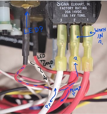
Not sure about the switch you point to as it also has three lugs peeking out when I would expect two for a built in LED? But they also don't actually say it is an LED, so it might be just a tiny bulb? I think most have stopped doing incancescent and gone to LED as cheaper to make and better overall?
I've got more questions than answers!
__________________
Richard
Why no RV year, make and floorplan on MY signature as we suggest for others?
I currently DO NOT have one!
|
|
|
|
|
09-10-2023, 02:04 PM
|
#29
|
|
Just Trying to Help
Join Date: Aug 2015
Posts: 526
|
dkoldman-
I'm fairly sure I can help you figure out the wiring and the parts list, if you'll give me some time to research more. For instance, the SPDT on/on switch on your current panel is a Sigma 1C-26-U switch, which you can buy on eBay now at this link. The wiring behind the panel is shown on this link. I need to look into this farther to see how you could do this with a plug-and-play wiring solution.
__________________
Mark
2008 Holiday Rambler Admiral 30PDD (Ford F-53 chassis)
2009 Honda Fit Sport
|
|
|
|
|
09-10-2023, 02:08 PM
|
#30
|
|
Winnie-Wise
Join Date: Mar 2022
Location: Wenatchee, WA
Posts: 332
|
That switch is actually just an on-off switch. The white wire is the ground for the LED light in the switch, thus why it lights up when it is on.
__________________
Bob & Shelly - 2022 Minnie 2529RG TT, 400AH LiFePo4 380W Solar
2016 RAM 3500 CC SRW SB Cummins
Remember, no matter where you go, there you are.
|
|
|
|
|
09-10-2023, 02:40 PM
|
#31
|
|
Just Trying to Help
Join Date: Aug 2015
Posts: 526
|
No1Hunter-
According to the panel wiring diagram, the pump LED is grounded through a different wire than the white one at position 3. The wires attached to positions 1 and 3 appear to be a pre-wire for a remote pump switch, such as the OP would like to install.
__________________
Mark
2008 Holiday Rambler Admiral 30PDD (Ford F-53 chassis)
2009 Honda Fit Sport
|
|
|
|
|
09-10-2023, 03:41 PM
|
#32
|
|
Winnebago Master
Join Date: Jun 2020
Location: Dallas, Texas
Posts: 1,051
|
Before I try to address any of the specific questions let me provide a few more material facts that I have observed.
1. The LED in the background is for water heater
2. New drawing shows the LED associated with the switch, they are two different parts only joined by the Red wire out of #2. The other white wire for the Water Pump LED jumps over to the LED for the Water heater. That white wire apparently for ground is not marked.
3. The big white wire going to #3 that looks like ground is marked but very light to read. my guess is GXL but I do not see the code. That same white wire has a splice and it may have been used by WBGO dealer to provide Ground for my Onan EC-30 AGS ( it was dealer installed when brand new)
4. The two red and one white wire all lead to a 15 pin connector ( 3x5) behind the panel.
But here is where it more confusing for me
I am gonna use #1, #2 & 3 from the actual switch
Using Voltmeter with Switch OFF
#1 (red probe) & #3 (black probe)=> -11.25 vdc
#2 (red probe) & #3 (black probe)=> -11.25 vdc
If I reversed the probes
#1 (black probe) & #3 (red probe)=> 11.25 vdc
#2 (black probe) & #3 (red probe)=> 11.25 vdc
Connecting #1 & #2 got nothing.
Using Voltmeter with Switch ON
#1 (red probe) & #3 (black probe)=> 0 vdc
#2 (red probe) & #3 (black probe)=> 0 vdc
My summary but not necessarily a material fact.
It looks like both red wires are hot with reverse polarity voltage when switch is off, when switch is ON Voltage goes to 0 and LED comes on as well as pump
__________________
2019 Sunstar 29ve; Toad Lincoln Navigator; RVi Brake 3; Roadmaster Nighthawk 676; Sumo Springs; Safe T Plus; Onan EC-30 AGS; Vmax 250ah AGM; T-Mobile Internet; Southwire EMS 44270/34951 Display 40301; Jet Flo Macerator; Alpine SPE500 Speakers; Visio M21D-H8R
|
|
|
|
|
09-10-2023, 03:44 PM
|
#33
|
|
Winnie-Wise
Join Date: Mar 2022
Location: Wenatchee, WA
Posts: 332
|
Quote:
Originally Posted by l1v3fr33ord1
No1Hunter-
According to the panel wiring diagram, the pump LED is grounded through a different wire than the white one at position 3. The wires attached to positions 1 and 3 appear to be a pre-wire for a remote pump switch, such as the OP would like to install.
|
Yes, but that is because the LED is not incorporate inside the switch in your diagram. If you look at the diagram, you will see a little dot under the switch labeled "Pump On." That is the LED in the drawing. You are talking about a completely different setup from what we are. Our LED indicator is incorporated inside the switch and actually lights up the switch when it is on. In order for the light to come on, it has to be grounded.
__________________
Bob & Shelly - 2022 Minnie 2529RG TT, 400AH LiFePo4 380W Solar
2016 RAM 3500 CC SRW SB Cummins
Remember, no matter where you go, there you are.
|
|
|
|
|
09-10-2023, 03:51 PM
|
#34
|
|
Winnebago Master
Join Date: Jun 2020
Location: Dallas, Texas
Posts: 1,051
|
Quote:
Originally Posted by l1v3fr33ord1
dkoldman-
I'm fairly sure I can help you figure out the wiring and the parts list, if you'll give me some time to research more. For instance, the SPDT on/on switch on your current panel is a Sigma 1C-26-U switch, which you can buy on eBay now at this link. The wiring behind the panel is shown on this link. I need to look into this farther to see how you could do this with a plug-and-play wiring solution. |
You must have a lot of confidence in yourself if you believe you can help me, after this... you may give up on electronics 
That switch you reference is exactly what I have so it confirms that my current is already SPDT.
Take your time, because if I can't get it on paper where I understand, I won't try. I will say that I hope the original switch can stay and that the new switch has integrated light, I don't care if it is LED light or not, just something to see that it is ON at night.
__________________
2019 Sunstar 29ve; Toad Lincoln Navigator; RVi Brake 3; Roadmaster Nighthawk 676; Sumo Springs; Safe T Plus; Onan EC-30 AGS; Vmax 250ah AGM; T-Mobile Internet; Southwire EMS 44270/34951 Display 40301; Jet Flo Macerator; Alpine SPE500 Speakers; Visio M21D-H8R
|
|
|
|
|
09-10-2023, 04:45 PM
|
#35
|
|
Winnie-Wise
Join Date: Mar 2022
Location: Wenatchee, WA
Posts: 332
|
Quote:
Using Voltmeter with Switch OFF
#1 (red probe) & #3 (black probe)=> -11.25 vdc
#2 (red probe) & #3 (black probe)=> -11.25 vdc
|
That proves the white wire is grounded.
__________________
Bob & Shelly - 2022 Minnie 2529RG TT, 400AH LiFePo4 380W Solar
2016 RAM 3500 CC SRW SB Cummins
Remember, no matter where you go, there you are.
|
|
|
|
|
09-10-2023, 04:52 PM
|
#36
|
|
Winnebago Master
Join Date: Jun 2020
Location: Dallas, Texas
Posts: 1,051
|
Update:
Another clue. The 3 wires 2 Red and one white all go into 15 pin connector 7,8, & 9. Not sure of actual order because I am not sure which is Pin 1 on connector. But is WBGO connector can be found it may tell where the wires go. It is too tight for me to get at the wires on the back side of connector.
One thing of note is on 12 of the 15 pins are used, of the 12 all are yellow except for one white. But the white for switch #3 goes to a yellow on back side of connector. It makes me think the white on Switch #3 is the inbound power to the switch.
__________________
2019 Sunstar 29ve; Toad Lincoln Navigator; RVi Brake 3; Roadmaster Nighthawk 676; Sumo Springs; Safe T Plus; Onan EC-30 AGS; Vmax 250ah AGM; T-Mobile Internet; Southwire EMS 44270/34951 Display 40301; Jet Flo Macerator; Alpine SPE500 Speakers; Visio M21D-H8R
|
|
|
|
|
09-10-2023, 05:02 PM
|
#37
|
|
Just Trying to Help
Join Date: Aug 2015
Posts: 526
|
dkoldman-
If I were investigating this for my own coach, I'd confirm the panel is wired to match page 2 of the diagram whose link I posted in post #29- all the way from connector C1 (on the left-hand side of that page) through the water pump switch and the separate LED. A simple physical exam of the panel, connectors and wires should confirm (or deny) the diagram.
If it matches the diagram then we can move on to how the circuit works.
<edit>
Quote:
Originally Posted by dkoldman
Update:
Another clue. The 3 wires 2 Red and one white all go into 15 pin connector 7,8, & 9. Not sure of actual order because I am not sure which is Pin 1 on connector. But is WBGO connector can be found it may tell where the wires go. It is too tight for me to get at the wires on the back side of connector.
|
Yes, by other wiring diagrams pins 7, 8 and 9 are the ones that connect the water pump circuit to the larger 12V system in a typical Sunstar/Vista. I could see that when I dug around in some older diagram sets. two of those pins refer to "WATER PUMP REMOTE SWITCH." This sounds like what you want to accomplish. Also, I passed by a notation in a Sunstar manual that said something like: "Some models have a second water pump switch in the wet bay or the bathroom." These are clues that maybe the wiring in your coach is already suitable for a remote switch, as you would like.
</edit>
__________________
Mark
2008 Holiday Rambler Admiral 30PDD (Ford F-53 chassis)
2009 Honda Fit Sport
|
|
|
|
|
09-10-2023, 05:02 PM
|
#38
|
|
Winnie-Wise
Join Date: Mar 2022
Location: Wenatchee, WA
Posts: 332
|
Quote:
|
One thing of note is on 12 of the 15 pins are used, of the 12 all are yellow except for one white. But the white for switch #3 goes to a yellow on back side of connector. It makes me think the white on Switch #3 is the inbound power to the switch.
|
Your test proved it is the ground. If it is "hot", then both red wires are grounds. Otherwise, you would not get a reading on your multimeter.
Look at it this way, the LED in the switch has to be grounded in order for it to light up when the switch is pushed to the "ON" position.
__________________
Bob & Shelly - 2022 Minnie 2529RG TT, 400AH LiFePo4 380W Solar
2016 RAM 3500 CC SRW SB Cummins
Remember, no matter where you go, there you are.
|
|
|
|
|
09-10-2023, 05:03 PM
|
#39
|
|
Winnebago Master
Join Date: Jun 2020
Location: Dallas, Texas
Posts: 1,051
|
Quote:
Originally Posted by No1Hunter
That proves the white wire is grounded.
|
It is over my pay grade. Why is the polarity reversed? I have to have Red probe on white wire to get 11.25vdc. Also, I just traced that same white wire to a connector on other side of connector it is yellow which normally for WBGO is hot.
__________________
2019 Sunstar 29ve; Toad Lincoln Navigator; RVi Brake 3; Roadmaster Nighthawk 676; Sumo Springs; Safe T Plus; Onan EC-30 AGS; Vmax 250ah AGM; T-Mobile Internet; Southwire EMS 44270/34951 Display 40301; Jet Flo Macerator; Alpine SPE500 Speakers; Visio M21D-H8R
|
|
|
|
|
09-10-2023, 05:10 PM
|
#40
|
|
Winnebago Master
Join Date: Jun 2020
Location: Dallas, Texas
Posts: 1,051
|
Quote:
Originally Posted by l1v3fr33ord1
dkoldman-
If I were investigating this for my own coach, I'd confirm the panel is wired to match page 2 of the diagram whose link I posted in post #29- all the way from connector C1 (on the left-hand side of that page) through the water pump switch and the separate LED. A simple physical exam of the panel, connectors and wires should confirm (or deny) the diagram.
If it matches the diagram then we can move on to how the circuit works. |
Just courious, how come I didn't see that drawing on WBGO Owners Resources?
That drawing is definitely what I have. I didn't see in post #29 before I was looking at the switch links and didn't see the last link as a new additional link.
But it is my panel and it is the 15 pin connector I was just referring to. Pins 7, 8, 9 should tell the story of where it goes on WBGO side. That Control Panel is an assembly that plugs into a WBGO Harness
__________________
2019 Sunstar 29ve; Toad Lincoln Navigator; RVi Brake 3; Roadmaster Nighthawk 676; Sumo Springs; Safe T Plus; Onan EC-30 AGS; Vmax 250ah AGM; T-Mobile Internet; Southwire EMS 44270/34951 Display 40301; Jet Flo Macerator; Alpine SPE500 Speakers; Visio M21D-H8R
|
|
|
|
|
|
|
Currently Active Users Viewing This Thread: 1 (0 members and 1 guests)
|
|
|
 Posting Rules
|
You may not post new threads
You may not post replies
You may not post attachments
You may not edit your posts
HTML code is Off
|
|
|
|
 » Recent Discussions
 |
|
|
|
|
|
|
|
|
|
|
|
|
|
|
|
|
|
|
|
|
|
|
|
|
|


 Linear Mode

