 |
|
 10-27-2023, 06:42 PM
|
#21
|
|
Winnebago Master
Join Date: Nov 2018
Location: Pflugerville/Austin, Tx
Posts: 7,543
|
Maybe some "word salad" will explain it as it is pretty simple when we only look at the parts involved and ignore those not involved?
Under the seat is the mode solenoid. Easy to spot as it is the shiny metal "can" with a big battery cable on each side and one or more small wires that bring a signal from the dash area. to make the solenoid move and close contacts between the left and right big lugs with the big cables.
There should be one small wire labeled LR and depending on solenoid type there may also be a second small wire FM. There are two basic versions of this solenoid, a 3 wire and 4 wire.
Idea is that when the engine is running a 12VDc signal comes down to the solenoid on LR, runs through the coil inside and goes to ground to make the contacts close.
On the 3 wire type, they used the mounting screws to get to ground but on four wire types, they also provide ground on FM.
If you don't want engine/chassis battery meeting coach battery, taking one of the big battery cables off with stop that. One can also take the LR wire off and then the solenoid doesn't get the signal to close!
But as mentioned, do you want the boost function? It is a rarely used function if you don't run the chassis battery used for starting the engine down to far to start! Pushing the dash switch connects the two battery groups together to "boost" or " jump start" the engine by using the coach batteries!
Jumper cables without having to get out jumper cables? All built in.
If I wanted to remove the connection and did not plan on running the start battery down, I would simply take a cable off and make a note to put it back if I got in a pinch and needed a jump start! I've never used mine on any RV, so not likely to miss it!!
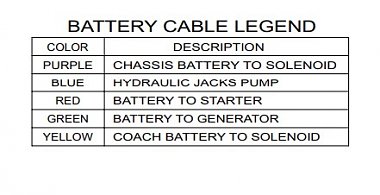
There is a bit of info which may make the cable sorting easier as they marked them when new and assuming the tape has not fallen off or been changed.
If you want to go for less getting under the seat, you also have the option of taking a battery cable off at the batteries.
See the yellow marking on the picture you posted? That cable goes to the solenoid and taking it off at either end opens the path for them to connect!
At the solenoid, there should be one yellow marked and one purple, so taking either off makes them not connect!
__________________
Richard
Why no RV year, make and floorplan on MY signature as we suggest for others?
I currently DO NOT have one! 
|

|

|
|
10-27-2023, 06:43 PM
|
#22
|
|
Winnebago Master
Join Date: Apr 2018
Location: Tucson, AZ
Posts: 1,216
|
Another way to install a DC-DC charger is just leave the isolation solenoid alone and put the DC-DC charger in the battery compartment. Put the positive battery cable on one side and have a short jumper made up to go from the DC-Dc back to the battery post. Ground the DC-DC to the chassis and install the trigger wire if equipped. The trigger wire can be attached to the same terminal as the one on your isolation solenoid. Jut FYI. You really don't need the DC-DC with your other options. I'll probably do it just because I'm a perfectionist.
__________________
Brian
2011 Winnebago Via 25Q on 2010 Sprinter Chassis
|
|
|
|
|
10-27-2023, 06:57 PM
|
#23
|
|
YTDave
Join Date: Sep 2023
Location: Gig Harbor
Posts: 18
|
Okay, so I had it backwards. Apparently I'm dyslexic. Ill informed or ignorant is probably a more accurate description, but you must admit that I did have a 50% chance of getting it right!
|

|
|
|
10-27-2023, 07:08 PM
|
#24
|
|
YTDave
Join Date: Sep 2023
Location: Gig Harbor
Posts: 18
|
Quote:
Originally Posted by Morich

Maybe some "word salad" will explain it as it is pretty simple when we only look at the parts involved and ignore those not involved?
Under the seat is the mode solenoid. Easy to spot as it is the shiny metal "can" with a big battery cable on each side and one or more small wires that bring a signal from the dash area. to make the solenoid move and close contacts between the left and right big lugs with the big cables.
There should be one small wire labeled LR and depending on solenoid type there may also be a second small wire FM. There are two basic versions of this solenoid, a 3 wire and 4 wire.
Idea is that when the engine is running a 12VDc signal comes down to the solenoid on LR, runs through the coil inside and goes to ground to make the contacts close.
On the 3 wire type, they used the mounting screws to get to ground but on four wire types, they also provide ground on FM.
If you don't want engine/chassis battery meeting coach battery, taking one of the big battery cables off with stop that. One can also take the LR wire off and then the solenoid doesn't get the signal to close!
But as mentioned, do you want the boost function? It is a rarely used function if you don't run the chassis battery used for starting the engine down to far to start! Pushing the dash switch connects the two battery groups together to "boost" or " jump start" the engine by using the coach batteries!
Jumper cables without having to get out jumper cables? All built in.
If I wanted to remove the connection and did not plan on running the start battery down, I would simply take a cable off and make a note to put it back if I got in a pinch and needed a jump start! I've never used mine on any RV, so not likely to miss it!!
There is a bit of info which may make the cable sorting easier as they marked them when new and assuming the tape has not fallen off or been changed.
Attachment 187696
If you want to go for less getting under the seat, you also have the option of taking a battery cable off at the batteries.
See the yellow marking on the picture you posted? That cable goes to the solenoid and taking it off at either end opens the path for them to connect!
At the solenoid, there should be one yellow marked and one purple, so taking either off makes them not connect! |
Now you're cooking with gas! Your suggestions are exactly the answer I was hoping to find. They seem simple and logical. Thank-you so much, I appreciate it tremendously!
|
|
|
|
|
10-27-2023, 07:11 PM
|
#25
|
|
YTDave
Join Date: Sep 2023
Location: Gig Harbor
Posts: 18
|
Quote:
Originally Posted by bigb
Those are actually wired in parallel and it's good that they are or else you would get 24 volts!
|
Okay, so I had it backwards. Apparently I'm dyslexic. Ill informed or ignorant is probably a more accurate description, but you must admit that I did have a 50% chance of getting it right!
Thanks
|
|
|
|
|
10-27-2023, 07:14 PM
|
#26
|
|
Winnebago Master
Join Date: Apr 2018
Location: Tucson, AZ
Posts: 1,216
|
Quote:
Originally Posted by Morich
On the 3 wire type, they used the mounting screws to get to ground but on four wire types, they also provide ground on FM.
|
I just installed a 4 wire Cole-Hersee and my terminals were not marked so I just connected them and it works fine, but I went to the C-H site to double check and while there are no indications of + or - on the coil terminals I did see that I was supposed to mount it with the capped end down! I mounted it cap side up just like the original Trombetta was mounted, I wonder if I should change it? I'll have to wait a few more days though for all my wounds to heal from replacing it in the first place, it was extremely hard to get to!
__________________
Brian
2011 Winnebago Via 25Q on 2010 Sprinter Chassis
|
|
|
|
|
10-27-2023, 07:24 PM
|
#27
|
|
YTDave
Join Date: Sep 2023
Location: Gig Harbor
Posts: 18
|
Quote:
Originally Posted by bigb
Another way to install a DC-DC charger is just leave the isolation solenoid alone and put the DC-DC charger in the battery compartment. Put the positive battery cable on one side and have a short jumper made up to go from the DC-Dc back to the battery post. Ground the DC-DC to the chassis and install the trigger wire if equipped. The trigger wire can be attached to the same terminal as the one on your isolation solenoid. Jut FYI. You really don't need the DC-DC with your other options. I'll probably do it just because I'm a perfectionist.
|
I appreciate your reply. My plan now is to throw the PD9245C converter/charger onto a shelf. Install a PD9145ALV Converter/Charger for the LiFePO4 batteries and have them charged when I'm on shore power and perhaps somewhat of a trickle charge out of the 100 Watt solar panel. In the meantime I also want to disconnect the charge coming from the alternator to the house batteries. Your straight up opinion on that idea would be appreciated because there seems to be some well informed people that are of the opinion that there is no harm in having the MB 220 amp alternator charge the lithium batteries.
Thank-you kindly for your time, opinion and suggestions.
|
|
|
|
|
10-27-2023, 07:26 PM
|
#28
|
|
YTDave
Join Date: Sep 2023
Location: Gig Harbor
Posts: 18
|
Quote:
Originally Posted by bigb
I just installed a 4 wire Cole-Hersee and my terminals were not marked so I just connected them and it works fine, but I went to the C-H site to double check and while there are no indications of + or - on the coil terminals I did see that I was supposed to mount it with the capped end down! I mounted it cap side up just like the original Trombetta was mounted, I wonder if I should change it? I'll have to wait a few more days though for all my wounds to heal from replacing it in the first place, it was extremely hard to get to!
|
Are we talking blood and deep scratches on the tops of your hands? Hahaha, that's pretty nasty...
Dave
|
|
|
|
|
10-27-2023, 07:30 PM
|
#29
|
|
Winnebago Master
Join Date: Apr 2018
Location: Tucson, AZ
Posts: 1,216
|
Quote:
Originally Posted by YTDave
I appreciate your reply. My plan now is to throw the PD9245C converter/charger onto a shelf. Install a PD9145ALV Converter/Charger for the LiFePO4 batteries and have them charged when I'm on shore power and perhaps somewhat of a trickle charge out of the 100 Watt solar panel. In the meantime I also want to disconnect the charge coming from the alternator to the house batteries. Your straight up opinion on that idea would be appreciated because there seems to be some well informed people that are of the opinion that there is no harm in having the MB 220 amp alternator charge the lithium batteries.
Thank-you kindly for your time, opinion and suggestions.
|
I'm going to leave mine connected at first without a DC-DC charger and monitor it. In Ron's video he put in a switch and amp meter but not sure I'd use it. I can draw the battery down low then go for a drive while watching on my Bluetooth Shunt, if it works once it will work always.
__________________
Brian
2011 Winnebago Via 25Q on 2010 Sprinter Chassis
|
|
|
|
|
10-27-2023, 07:32 PM
|
#30
|
|
Winnebago Master
Join Date: Apr 2018
Location: Tucson, AZ
Posts: 1,216
|
Quote:
Originally Posted by YTDave
Are we talking blood and deep scratches on the tops of your hands? Hahaha, that's pretty nasty...
Dave
|
Cuts and scratches, pulled muscles, skinned elbow and a headache from rolling my eyeballs up into the top of my head to see. Not to mention working one handed as there is not enough room to get in there with two arms.
__________________
Brian
2011 Winnebago Via 25Q on 2010 Sprinter Chassis
|
|
|
|
|
10-27-2023, 08:02 PM
|
#31
|
|
Winnebago Master
Join Date: Apr 2018
Location: Tucson, AZ
Posts: 1,216
|
BTW there are lots smarter folks than me over on the Sprinter forum, those folks build some serious off grid campers and they have assured me that for my proposed 200ah battery (puny to them) I won't need a DC-DC charger as long as I have at least one method to top off the LiFePO4. With a Li converter and a portable Smart Charger (that I have wired in so I don't have to open the step to connect) I'll have 2.
__________________
Brian
2011 Winnebago Via 25Q on 2010 Sprinter Chassis
|
|
|
|
|
10-28-2023, 08:14 PM
|
#32
|
|
YTDave
Join Date: Sep 2023
Location: Gig Harbor
Posts: 18
|
If I could trouble one of you connoisseurs de 12 volts to have a look at the crude diagram and tell me if the last wire goes to? I suspect it goes back to the alternator, but as you've no doubt noticed by now... I'm not at all savvy when it comes to this stuff. And of course, if you think or suspect that this whole thing looks all wrong, feel free to correct me!
I've written "so, this ground must go to???"
I should have added that I wrote "left side" and "right side" because I plan to replace this mess with a single LiFePO4 battery and if it doesn't work out, I may have to go back to two AGM batteries or something and I'll need this diagram to refer to because there's absolutely no way I'll remember this mess.
Pretty filthy in there eh!
Thanking you all again...
|
|
|
|
|
10-28-2023, 09:35 PM
|
#33
|
|
Site Team
Join Date: Sep 2009
Location: Spring Branch, TX
Posts: 7,840
|
I could be wrong, but I don’t think that neg goes to the alternator. The alternator grounds to the chassis. I’d be surprised if that positive cable marked as coming from the alternator is accurate either.
I need to check the wiring diagram to be more confident of my comments and we’re on the road right now so I haven’t had the time. I’m sure someone better informed will respond.
__________________
2017 Winnebago Adventurer 37F
2016 Lincoln MKX Toad
|
|
|
|
|
10-29-2023, 08:05 AM
|
#34
|
|
Winnebago Master
Join Date: Apr 2018
Location: Tucson, AZ
Posts: 1,216
|
That all looks correct as labeled, not sure where that second negative wire goes but it doesn't really matter as long as you connect it to negative on the new battery. The positive that you labeled "from alternator" does come from the alternator but not directly, it actually comes from the battery isolation solenoid where it is identified again with yellow and a different fat wire comes from the alternator and connects to the other side of the BIS.
Which battery are you going with? I still have not decided which one (or 2) I'm getting.
Are you doing a monitor with a shunt?
__________________
Brian
2011 Winnebago Via 25Q on 2010 Sprinter Chassis
|
|
|
|
|
10-29-2023, 08:57 AM
|
#35
|
|
YTDave
Join Date: Sep 2023
Location: Gig Harbor
Posts: 18
|
Quote:
Originally Posted by bigb
That all looks correct as labeled, not sure where that second negative wire goes but it doesn't really matter as long as you connect it to negative on the new battery. The positive that you labeled "from alternator" does come from the alternator but not directly, it actually comes from the battery isolation solenoid where it is identified again with yellow and a different fat wire comes from the alternator and connects to the other side of the BIS.
Which battery are you going with? I still have not decided which one (or 2) I'm getting.
Are you doing a monitor with a shunt?
|
I suspected that the wire "from the alternator" ran through the battery isolation switch. Seems logical...
I'm leaning heavily towards the following...as described on Amazon...
" 12V 100AH Self-Heating LiFePO4 Lithium Battery with Touchable Smart Display & APP Monitoring, Built-in 100A BMS,1280W Load Power, 5000+ Cycles , Perfect for RV/Camper, Solar, Home Energy Storage". I like the automatic self-heating feature that will be activated by the BMS when the battery is connected to a charger at -4°F to 4°F. It also has a Bluetooth feature for displaying battery information on your phone. It's currently (pun intended) priced at $320.00 on Amazon.
I like the heat feature...as I gaze at the thermometer and it's 31 degrees here in Gig Harbor. I like the blue tooth monitoring feature because I don't have a clue as to how to hook up a shunt and I'm trying to keep this as simple as possible. And of course, if for some reason this turns out to be a disaster, I can throw the whole mess in the garbage and start from scratch without having spent too much money.
I'm also debating the merits of adding another solar panel, but I want to get the battery project done before I tackle that idea. I had a couple of solar panels on my trawler for many years and they sure helped when we were anchored in a little bay somewhere over a period of days...
Thank-you for your reply. I appreciate your contribution to this project and if you have any better ideas, please feel free to offer them up.
Cheers!
|
|
|
|
|
10-29-2023, 09:30 AM
|
#36
|
|
Winnebago Master
Join Date: Apr 2018
Location: Tucson, AZ
Posts: 1,216
|
Quote:
Originally Posted by YTDave
I suspected that the wire "from the alternator" ran through the battery isolation switch. Seems logical...
I'm leaning heavily towards the following...as described on Amazon...
"12V 100AH Self-Heating LiFePO4 Lithium Battery with Touchable Smart Display & APP Monitoring, Built-in 100A BMS,1280W Load Power, 5000+ Cycles , Perfect for RV/Camper, Solar, Home Energy Storage". I like the automatic self-heating feature that will be activated by the BMS when the battery is connected to a charger at -4°F to 4°F. It also has a Bluetooth feature for displaying battery information on your phone. It's currently (pun intended) priced at $320.00 on Amazon.
I like the heat feature...as I gaze at the thermometer and it's 31 degrees here in Gig Harbor. I like the blue tooth monitoring feature because I don't have a clue as to how to hook up a shunt and I'm trying to keep this as simple as possible. And of course, if for some reason this turns out to be a disaster, I can throw the whole mess in the garbage and start from scratch without having spent too much money.
I'm also debating the merits of adding another solar panel, but I want to get the battery project done before I tackle that idea. I had a couple of solar panels on my trawler for many years and they sure helped when we were anchored in a little bay somewhere over a period of days...
Thank-you for your reply. I appreciate your contribution to this project and if you have any better ideas, please feel free to offer them up.
Cheers!
|
That's a nice battery Dave. I'm still deciding if I want 100 or 200ah. Not worried about heating it as we live in the desert and store indoors. From what I have read as a Li battery cools is is kind of self protecting anyway as the action inside kind of naturally slows down, but charging under extreme cold can cause damage.
__________________
Brian
2011 Winnebago Via 25Q on 2010 Sprinter Chassis
|
|
|
|
|
10-29-2023, 05:42 PM
|
#37
|
|
Winnebago Master
Join Date: Oct 2017
Location: Elk Grove, CA
Posts: 3,583
|
I admit that I haven't read every word of this post, nor have I watched the videos but I don't understand what's so complicated about wiring in a DC-to-DC charger. It's certainly no more complicated than the rest of your project.
I installed a Renogy unit in my Ford Van and it wasn't difficult. The only unique thing is what's known as the DC+ connection to the alternator that lets the charger know that the alternator is actually running. It's just a matter of running a small (18-16AWG) wire from the charger to the alternator and splicing it into the correct wire from the alternator. The Renogy manual has a diagram, but, if you're unsure, most mechanics should be able to guide you or make the splice for you. The splice is a 5 minute job once the wire's been run (easy with that small of an AWG).
Other than that, it's pretty much +/- from the alternator to the DC-to-DC Charger and +/- to your house batteries from the charger with a couple of fuses. See page 10 of the Renogy manual.
https://www.renogy.com/content/RNG-D...060-Manual.pdf
I would think that other brands are similar.
__________________
Bob C
2002 Itasca Suncruiser 35U
Workhorse Chassis
|
|
|
|
|
10-29-2023, 08:30 PM
|
#38
|
|
YTDave
Join Date: Sep 2023
Location: Gig Harbor
Posts: 18
|
Quote:
Originally Posted by BobC
I admit that I haven't read every word of this post, nor have I watched the videos but I don't understand what's so complicated about wiring in a DC-to-DC charger. It's certainly no more complicated than the rest of your project.
I installed a Renogy unit in my Ford Van and it wasn't difficult. The only unique thing is what's known as the DC+ connection to the alternator that lets the charger know that the alternator is actually running. It's just a matter of running a small (18-16AWG) wire from the charger to the alternator and splicing it into the correct wire from the alternator. The Renogy manual has a diagram, but, if you're unsure, most mechanics should be able to guide you or make the splice for you. The splice is a 5 minute job once the wire's been run (easy with that small of an AWG).
Other than that, it's pretty much +/- from the alternator to the DC-to-DC Charger and +/- to your house batteries from the charger with a couple of fuses. See page 10 of the Renogy manual.
https://www.renogy.com/content/RNG-D...060-Manual.pdf
I would think that other brands are similar. |
If I was building this whole thing on a sheet of plywood, the wiring would look as easy as it does in a wiring diagram. But, some of this gadgetry is located under the passenger seat inside the vehicle and that means running cable or wire from under the seat to under the dash or through the firewall. Then the dc2cd charger itself needs to be located somewhere with decent ventilation and space. Where am I gonna put it and is it gonna mean running cable through a wall and require drilling holes, rubber grommets etc. The project starts to look like a nasty rabbit hole that I don't want to go down into if I can avoid it.
I can figure it out with a wiring diagram, but the physical installation itself needs to be workable. It needs to look good, tidy and it has to work efficiently. That's what I'm wrestling with...
Dave
|
|
|
|
|
10-30-2023, 11:35 AM
|
#39
|
|
Winnebago Master
Join Date: Oct 2017
Location: Elk Grove, CA
Posts: 3,583
|
Here's a new Winnieowners post you may not have seen:
https://www.winnieowners.com/forums/...-new-post.html
__________________
Bob C
2002 Itasca Suncruiser 35U
Workhorse Chassis
|
|
|
|
|
10-30-2023, 03:03 PM
|
#40
|
|
Winnebago Camper
Join Date: Feb 2020
Posts: 10
|
Another reference I recommend to consult.
I recently completed a LiFePO upgrade on my 2019 Navion 24G
I followed the guideline . mods description on the https://www.viewnavion.com/ website.
The information is very good and the conversion worked very well.
I just completed a round trip from Ormond Beach, FL to Austin, TX and tested the upgrade - it worked flawlessly.
Yes you do need to investigate and learn a few things as I had to but it was interesting.
__________________
MarkW
2019 Navion 24G
|
|
|
|
|
|
|
Currently Active Users Viewing This Thread: 1 (0 members and 1 guests)
|
|
|
 Posting Rules
|
You may not post new threads
You may not post replies
You may not post attachments
You may not edit your posts
HTML code is Off
|
|
|
|
 » Recent Discussions
 |
|
|
|
|
|
|
|
|
|
|
|
|
|
|
|
|
|
|
|
|
|
|
|
|
|


 Linear Mode

