Journey with Confidence RV GPS App RV Trip Planner RV LIFE Campground Reviews RV Maintenance Take a Speed Test Free 7 Day Trial ×
 

Go Back   Winnebago Owners Online Community > WINNEBAGO TECH & TOW > Plumbing | Systems and Fixtures
Click Here to Login
Register FilesRegistry Blogs FAQ Community Calendar Today's Posts Log in

Reply
 
Thread Tools Search this Thread Display Modes
 
Old 07-14-2023, 10:56 AM   #1
Winnebago Camper
 
Join Date: Jul 2023
Posts: 7
Water Pump problem 1992 Minnie Winnie WF527RQ

I am trying to get my brother in law's 1992 Minnie Winnie WF527RQ motorhome up and running after sitting for 6 years. Mileage 26,000.

Currently I am trying to get the shurflo water pump system working. After cleaning the common ground points (under chassis by driver rear, and under chassis by passenger rear tire) I now have power to the white and green wires plugging into the Shurflo pump. I have 12 volts present. The pump runs when I bench tested immediately, but for some reason doesn't run at all when installed??

Appears, there are three switches (bathroom, outdoor shower, and monitor panel). The monitor and outdoor shower are DPDT on/off (not momentary). There appears to be no relays or latching controllers that can be found or present in the wiring diagrams.

Puzzling, the monitor switch appears to be DPDT that has a 3 position rocker (left, center, to the right). The pump light stays on no matter what position the switch is in.

What am I missing? Next steps to get pump running? Is there a relay or controller hidden somewhere on a 1992 Minnie Winnie --I've studied the wiring diagrams and looked everywhere I can think of.

I would appreciate any help. Hoping to find a owner of a similar coach who could tell me how these switches control the water pump. I don't understand why the bathroom and outdoor shower switches are two positions (on/off??) and the monitor panel is three positions.
Why would you have a monitor rocker that has two different on positions??

Sorry for all the info at once, Mark
Attached Thumbnails
Click image for larger version

Name:	Monitor panel water pump switch front.jpg
Views:	28
Size:	235.2 KB
ID:	186649   Click image for larger version

Name:	Monitor panel water pump switch back.jpg
Views:	29
Size:	214.5 KB
ID:	186650  

Washington is offline   Reply With Quote
Old 07-14-2023, 02:17 PM   #2
Winnebago Watcher
 
Join Date: Jul 2023
Posts: 1
Not sure if this helps, but I have a 1996 Minnie Winnie and the water pump switch is an ON/Off switch with no additional switches in bathroom / exterior shower.
Also you mentioned both wires going to water pump are 12v (hot) I think that may be a problem, one should be a ground. Perhaps try a on/off switch in place of the 3 way and see what happens at the pump
Good luck
JShort is offline   Reply With Quote
Old 07-14-2023, 02:49 PM   #3
Winnebago Master
 
Join Date: Nov 2018
Location: Pflugerville/Austin, Tx
Posts: 7,537
I think it is great when we get as much good info at once as you have!!
Sounds like you have done much of the right stuff that we sometimes have to drag out of folks!
But that's the good side and I STILL want to ask some questions as this is one that gets tricky! Have you worked on any light situations in a house where there are more than one switch to turn the light on? This is much the same and we need to do the same checking.

You mention power to the pump, but what about ground? I assume when bench testing you had to have power and ground and the pump has to have that full circle or circuit for the power to someway find a path from the battery through the switches and back to ground. Basic and I suspect you knew that but what I wanted to point out it that path is likely set up to go in an odd way, so that it gets power to the pump, no matter which way any one of the switches is left set.

I might first want to be sure the pump works when it gets battery and ground after it is installed as there are two things which "may" be keeping it from runningeven when wiring is good, so I would want to make sure of those before chasing wiring too hard?
Your choice, of course but there might be something like the pump got jammed or the pressure switch is thinking it has built enough pressure and shutting it down.
Thinking of small points that electrical testing mightnot change?

Can you see a way to get battery and ground onto the pump wiring while it is installed, just to make sure all the physical parts are still willing to go?
Maybe a plug that you can pull apart easily and check just the motor and pessure switch?

Then there may be some help on the way Winnebago labled the wires with ID stamped on them!
Click image for larger version

Name:	wire ID.jpg
Views:	30
Size:	30.2 KB
ID:	186651

This can help as when we look at the drawings, we can match up the wire ID on the drawings and wire and also use this chart to "decode where that wire goes to and from!
https://www.winnebago.com/Files/File...ical_guide.pdf

So it looks like there were two different wiring vertions on that RV, so sorting which may be a first stop. But if you spot the wire ID on a wire, go to the decode chart and find where that wire comefrom and goes to as it will often tell you which should be power!
Maybe the power and ground got swapped at some point or something simple that drives us crazy? See on sheet 2 at top right where it shows the wire ID JA?
The chart shows that JA comes from power to the center pin on that connector to make less guessing about whether we should find battery or ground there!
A "cheat" to know about using the chart is the way we can search for a term.
Hit "ctrl and h" at the same time to get a drop down box. Then input the term like JA and it brings a list to scroll through all the points where we find JA in the list. Not totally happy as JA also shows in lots of places where JACK is listed but it can cut the chase a bunch?

What I might guess is happening is that there is a point like that three pin connector that has power on AG perhaps but that power has to go to another switch and come back at times. I'm guessing that there is some point where one pin of a connector is not passing the power or ground! Guessing without testing!!


Are you up on how to read the drawings on where one plug or wire meets the next?
This small note tells us where to move to a different page or point to continue following the trail! It gives a sheet number then a horizontal and verticl to follow where they cross to find the trail again?
Click image for larger version

Name:	switch.jpg
Views:	36
Size:	48.9 KB
ID:	186652

My suggestion would be to start at either battery or the pump and sort which is failing to get there, check that the pump DOES actually run to make sure it is electrical or mechanical trouble, then follow the trail?

Hope that makes some sense and it helps sort the thing.
Warning? This does get into some connections going back and forth between the switches that don't seem to make sense at times!
The idea is that when one of three switches is left turned off, we don't have to go inside to turn the pump on! Nice but it takes a dedicated trooper to follow the trail!
__________________
Richard
Why no RV year, make and floorplan on MY signature as we suggest for others?
I currently DO NOT have one!
Morich is offline   Reply With Quote
Old 07-14-2023, 02:53 PM   #4
Winnebago Master
 
Join Date: Nov 2018
Location: Pflugerville/Austin, Tx
Posts: 7,537
Quote:
Originally Posted by JShort View Post
Not sure if this helps, but I have a 1996 Minnie Winnie and the water pump switch is an ON/Off switch with no additional switches in bathroom / exterior shower.
Also you mentioned both wires going to water pump are 12v (hot) I think that may be a problem, one should be a ground. Perhaps try a on/off switch in place of the 3 way and see what happens at the pump
Good luck
Yes, I agree that sounds like it points to the problem, but we will get power showing on both sides of a good switch if it is closed and that outgoing wire is not getting full circle back to ground! the switch is not bad but the path from that switch may need to go some other places to get back to ground to complete the circuit!
Hope that makes sense?
Part of the problem may be first finding which option this specifc RV has as there shows two different wiring setups. Your two RV may/may not match.

Midline or lowline RV? Option 1,2 or 3?
Attached Images
 
__________________
Richard
Why no RV year, make and floorplan on MY signature as we suggest for others?
I currently DO NOT have one!
Morich is offline   Reply With Quote
Old 07-14-2023, 06:45 PM   #5
Winnebago Master
 
Join Date: Nov 2018
Location: Pflugerville/Austin, Tx
Posts: 7,537
You mention three switches? Does that mean you DO have a switch at an exterior shower?

Looking at what parts of the drawings we might begin to leave out? If no exterior shower option, then this is info we can ignore, or do we need to consider it as well?
I read this option as either with switch and wiring runs through it or if no switch it simply plugs top two pin connector to bottom two pin connector.

Switch at exterior shower?
Click image for larger version

Name:	ext sw.jpg
Views:	32
Size:	43.2 KB
ID:	186654

The problem with working from drawings only is that it is much harder to spot which options to use and which to ignore. If you can locate some wire ID on some of the switches, that will let you begin to sort which switch they call number one versus number two or three.
Like wire FJ runs from switch 2 to switch 1 but from here I struggle to spot Where either is actually located on the RV.

Hoping you can have a much better view!
__________________
Richard
Why no RV year, make and floorplan on MY signature as we suggest for others?
I currently DO NOT have one!
Morich is offline   Reply With Quote
Old 07-14-2023, 08:13 PM   #6
Winnebago Camper
 
Join Date: Jul 2023
Posts: 7
WOW...thanks for all the feedback.

I have taken the pump out and bench tested---works perfectly and immediately begins running.

The issue is somewhere in the wiring.

I have almost 14 volts at the house battery (plugged in), however my tester shows 12 volts at the pump. White is positive and green is negative.

Someone had suggested testing the voltage at the pump with the pump connected and switch turned on. Yikes....voltage dropped to practically nothing. So checked again with pump disconnected...12.05 volts. Hmmm So I tried hooking up a 12 volt bulb...wouldn't even light up a little bulb!!!! So here's the problem...I guess I thought if I saw 12 volts on the meter all was good...wrong.

Without success, I've tried over the last two weeks to trace the white and green that feed the pump and also tried tracing the wires coming from the powercenter 15amp fuse, with no success, as well as switches.
Thought: I had tested the fuse blades of pump fuse in powercenter for 12 volts...I wonder if that's a false impression of voltage without a load. I should try hooking a load directly to the fuse blades to see if voltage drops. What does it mean when voltage drops to practically nothing with a load?

As suggested, I tried reading the wiring diagrams and searched for key words like relay, module water pumps, to find wires that I could try to chase.

I thought I had found to two areas of chassis grounding--cleaned them all. All battery terminals are clean. Since 12 volts runs through the power center, could that somehow limiting current flow?

According to the wiring diagram, the water pump circuit is an "isolated circuit." Would it be just easier to run two 10 gauge wires to the house battery, with an Intellic water pump control and run some 14 gauge to a couple of switches? Totally bypassing the existing water pump circuit. https://www.amazon.com/Intellitec-00...aps,288&sr=8-1 I was hoping to just fix the issue, but have been unsuccessfull.

Appreciate your help, Mark
Washington is offline   Reply With Quote
Old 07-14-2023, 08:31 PM   #7
Winnebago Camper
 
Join Date: Jul 2023
Posts: 7
The wiring diagrams I've been using are for the DL Minnie Winnie 1992.
https://www.winnebago.com/Files/File...ram/Wiring.htm
Washington is offline   Reply With Quote
Old 07-15-2023, 07:56 AM   #8
Winnebago Master
 
Join Date: Nov 2018
Location: Pflugerville/Austin, Tx
Posts: 7,537
Sounds like you have what I call a "high resistance open"!
The wire is not fully open so you get enough current through to let a meter read it. But when the motor tries to use it and needs far more than the meter, there is not enough contact to let enough current flow for the motor to run!
OR, an easy one to walk past is a bad ground as that power that the meter reads may be enough to work but it can't if the other wire going bad to ground doesn't let it have a full circle, (open circuit?) So when we get to a connection, it can save us time if we check the power, look for clean conntact and also look for that return to ground. That's where having the exact right drawing can be a big help becasue it should tell us what color wire and we can check that with the wire ID and also we should know which direction to klook on that wire and expect to see battery. If we see battery looking "left" we can then look "right" and have to see ground!
One way to cut the chase in half, if we know the full circuit is to go to a point somewhat in the middle and check a connector, looking toward the battery and toward the ground.
On a bad circuit,one will be missing or funky, so we know to move in that direction.

I never know the folks on the other end of posts, so don't let this offend if I'm telling you lots of things you already know. Lots of folks reading along may not know and I like to make it clear what I'm getting at when they may read it two years from now!
And it is always true that what I do is not the only way, just the way I currently see doing the job!
Lots of different ways to paint a house!

This is something that can happen in lots of ways but one of the more common would seem to be where the pins of connectors get slightly corroded and only make a half hearted connection, rather than a clean solid one.

How to find and fix can be shotgun and maybe quick or slower and testing each connection along the path. Sometimes a combo of each works good as how and where the connections are located and what it takes to get to them makes a big difference! Of course, it could also be as simple as one of the switches being corrroded, worn, etc. Those switches are almost always easy to find but getting them out of the wall can be a trick, at times.

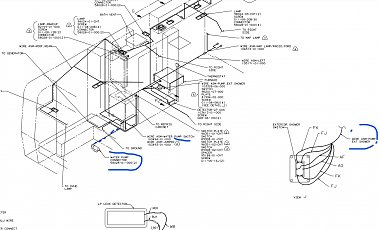
See up there on post 5 where it shows that connection as "under shower"? Next big question comes down to what does it take to get "under the shower" to that connection!
So before you start doing the duty to take things apart to get under the shower, I like to first get down solid which parts you will actually have on YOUR specific RV as each RV may have different options and number of switches.
Mid level, low level, or no exterior shower at all, is what I'm seeing in the notes, so finding which you actually have on YOUR RV can cut the chase really quickly if you don't have that part.
Knowing which parts to expect to find, like how many switches you have can let you skip over looking for parts you don't have!
My work has been in repair on really complex wiring things where you may start with 15-20 sheets and spread them out on the floor to start tracing! That made me learn to first sort out what I could ignore as not part of the problem!
Good to check and clean each connection but not if it means taking a wall apart??

I think the drawings will give a pretty good shot at locating each connection but then knowing if that space is something you can get to easy enough to make it practical takes hand on looking.

As a second way to get some info on where they may have put things, have you found the "installation" drawings on that same list?
They give us the schematic for wire by wire info but then the install set can give us a better idea of the physical location of things. I hate them as they usually get so messing and hard to read which way the tiny little line goes but if you can see the wire AND the drawing it makes more sense of things!
https://www.winnebago.com/Files/File...992/105169.pdf

Down on sheeet 7? But where is the shower? That has to be the hands on looking part!
Click this snip to get better view!
Click image for larger version

Name:	install.jpg
Views:	31
Size:	200.4 KB
ID:	186655

The thing about this pump circuit that makes it tricky is that it is not just an on/off deal with simple switches that open or close. But when one switch is open to turn the pump off, we also want to be able to turn it on from a different switch, so we have to have double throw switches!
That means when you check a switch is letting power through in one position, you also have to check it will let power through on the second path when left thrown in the other position!

A far quicker way to sort this might be worth the time as "shotgun" work may find the problem.
This requires ALL the switches to work ALL the time. So if you have three switches, you "might" find the whole thing is bad only when one switch is set to some specific position! Since it could be a bad switch or a bad wire connection, one might try setting switch one to left or right, then go to the other two switches and find if they work. If not go back to that first switch and repeat the test again. Kind of looking for luck but if one goes through flipping each switch and then trying the others, you might find one combo that works while other combos fail??

I'll let you decide what is whorth the time because either way either testing slowly or shotgun may turn out quicker! It's hot and I hate to think about getting under the shower, etc, if I might get lucky by flipping the swiches to find I can cut the chase a bunch!

You've got a tricky one, though! Like lights in a house that have several switches, I hate them as I don't do it often enough so that I have to set and think really hard when I do get into one!
__________________
Richard
Why no RV year, make and floorplan on MY signature as we suggest for others?
I currently DO NOT have one!
Morich is offline   Reply With Quote
Old 07-15-2023, 06:15 PM   #9
Winnebago Camper
 
Join Date: Jul 2023
Posts: 7
Success!
I can't thank everyone enough for all your help and guidance---awesome community I now have a working water pump and all three switches work!

Here's what I found/did:

1) 92 Minnie Winnie's have about 10 wires that go to a common ground point under the chassis near rear tires--the bracket welded to the frame and connections were corroded. Remove, clean, reinstall

Also under chassis in front of rear tire is another slew of green grounds--remove, clean, and reinstall (although not part of the problem)

2) After checking all the connectors using the wiring diagrams, I found one lead on a 4 connector that had backed away and was making marginal contact. This was a positive lead.

Lessons Learned: Having 12 volts at a connection doesn't necessarily mean all is good. Be prepared to have patience and investigation going through pathways, connections, switches etc. In my case, I didn't find out this was the case until it was suggested to measure voltage with switches on and pump connected. Voltage dropped to practically nothing--too much resistance with bad grounds and loose connector pin.

The wiring diagrams are invaluable in finding to and from, connector locations etc. Once I saw the green wire that fed negative to the pump didn't go through a maze of wiring, just to the frame common ground point, I tried to eliminate this path first. Ran a wire from ground to the pump and then measured voltage--went to almost 14 volts and the pump puttered to life. The pump light indicator on the monitor panel now only lights when the pump is actually running...not just connected. A high resistance path complicated everything.

After confirming a good ground path, I painstakingly checked all the connectors, I would never have found a pin that had backed away on a positive lead.

The waterpump wiring on these older motorhomes is much more complicated that more modern coaches that use momentary switches and latching relays. All three switches are not independent, like a latching relay. You have to follow the path all the way through each of the 3 switches to chase an issue.

Thanks again everyone, Mark
Washington is offline   Reply With Quote
Old 07-15-2023, 08:36 PM   #10
Winnebago Master
 
Join Date: Nov 2018
Location: Pflugerville/Austin, Tx
Posts: 7,537
All's welll that ends well? Except for all the work in between!

Good deal to make some progress!
__________________
Richard
Why no RV year, make and floorplan on MY signature as we suggest for others?
I currently DO NOT have one!
Morich is offline   Reply With Quote
Reply

Tags
water, water pump


Currently Active Users Viewing This Thread: 1 (0 members and 1 guests)
 

Posting Rules
You may not post new threads
You may not post replies
You may not post attachments
You may not edit your posts

BB code is On
Smilies are On
[IMG] code is On
HTML code is Off
Trackbacks are Off
Pingbacks are Off
Refbacks are Off


Similar Threads
Thread Thread Starter Forum Replies Last Post
Could use some help with streaming to TV or Entertainment System STCLARKE Winnebago Travel Trailers 28 07-04-2022 09:29 AM
HELP! How to use/store/use Winne Paseo in winter weather Rgossen Winnebago General Discussions 7 01-20-2021 07:59 PM
Could I have a dead battery? Please help Scorn General Maintenance and Repair 11 09-23-2019 04:54 PM
2013 Winnebago Ellipse 42GD - Could use advice midwest22 Winnebago Class A Motorhomes 10 09-30-2018 06:07 PM
Could use some help re batteries The Shadow Electrical | Charging, Solar and Electronics 25 03-18-2005 03:42 PM

» Featured Campgrounds

Reviews provided by

Disclaimer:

This website is not affiliated with or endorsed by Winnebago Industries or any of its affiliates. This is an independent, unofficial site.


All times are GMT -6. The time now is 11:50 PM.


Powered by vBulletin® Version 3.8.8 Beta 1
Copyright ©2000 - 2024, vBulletin Solutions, Inc.