 |
 03-31-2024, 09:03 PM
|
#1
|
|
Winnebago Camper
Join Date: Dec 2023
Posts: 23
|
Inverter install on prepped 2024 Micro Minnie 2108DS
This thread could go over in the electrical section, but I put it here to feed the new Micro Minnie 2108DS owners that may have questions about how to work with their inverter prepped trailer. Feel free to move this though.
Since the inverter prep (and a few other things) are new on the 2024 non-FLX Micro Minnies, I thought Id post up my discoveries and how I installed my Renogy 2000W inverter. I think the biggest help I can offer is what I did with the loop of romex under the Prepped for Inverter cover that's just inside the passenger side pass-through compartment door. I started with contacting Winnebago, and lets just say thats a crap shoot. After one email exchange, I never got a reply to my second question. So I called and got a very helpful lady who sent me the drawings I initially thought I needed. Then life got busy before I got back to pondering the project, and a couple days later (a month after my first inquiry) I got the email reply. I asked for a couple more drawings, and got them right away.
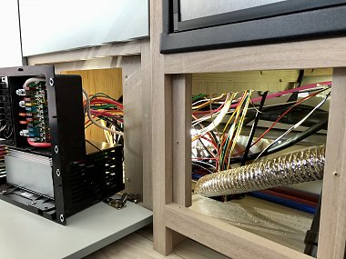
First, here's the finished product to decide if you even want to read any further.
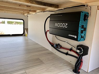
This is just the 12v distribution with all new marine grade connectors vice the unsealed crimp connectors that will corrode.
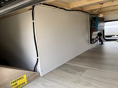
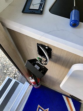
One end of the romex goes directly to the power distribution panel that holds the 115v circuit breakers in it (below the stove top). After looping up through the pass through compartment, the other end of the romex goes to the GFI outlet immediately inside the door on the left side attached to the sink cabinet. The two outlets on either side of the bed in the 2108DS model are fed from that GFI outlet. Honestly, figuring this out involved a fair amount of cable chasing, inspecting behind the dist panel and under the trailer, and some light tugging on the romex ends after marking both entry points with a silver sharpie. I marked the romex with a line at the entry points to the flex conduit in the pass through compartment and in the floor behind the breaker panel. Then since the romex isnt secured between those points, a light to moderate tug on the romex inside would move the romex slightly in the pass through. I could tell which of the two romex sections in the pass through moved, and therefore, I knew which one went to the back of the GFI outlet, and thats the one I wanted to connect to the inverter! I cut the romex loop short on the lead that went to the breaker panel leaving about 18 sticking into the pass through, which left the other section that went to the GFI outlet about 9ft long. The 18 section was capped with wire nuts, taped, and marked with a sharpie to clearly say where it went. That run can be used in the future if I want to add the oven onto the inverter. With the other section being 9ft long, I then had enough length to reach the drivers side of the pass through, which is where I wanted to mount the inverter. This is why I didnt just cut the romex in half. I chose to mount the inverter on the drivers side mainly to keep the 1/0 battery run as short as possible.
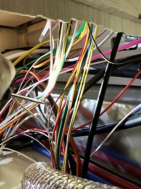
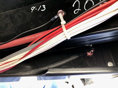
The pic below has the screwdriver pointing at the black romex that goes over to the breaker panel.
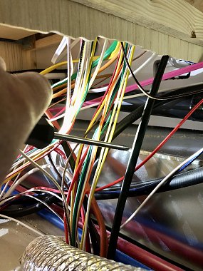
And in this pic I'm pointing at the black romex that goes up and then across to the GFI outlet.
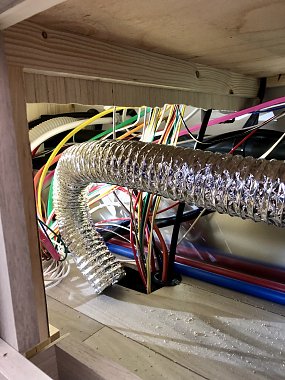
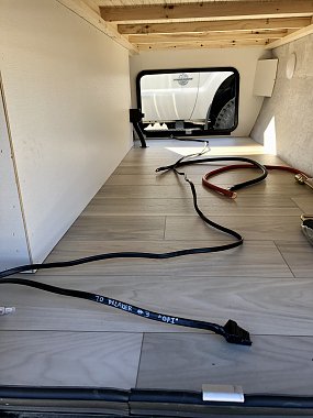
I threw in this pic to show folks the furnace ducting that is stuck down through the same hole that the wiring goes into. This shows the routing of heat below the floor.
Short romex has the writing "TO BREAKER #3 GFI", and you can see how nice and long the other part of the loop is that allows it to reach the other side.
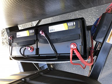
The rest was fairly straight forward. I didnt connect the 1/0 battery + lead to the battery cutoff switch in the pass through because all the trailer battery leads are 6awg, which would cook if I ran the 2000W inverter anywhere close to half-throttle. So the red battery lead ran from the inline circuit breaker mounted under the inverter up to the + terminal on the drivers side AGM battery. The black 1/0 lead ran from the inverter to frame ground under the trailer about 2 ft from where the AGM battery - lead is connected. (cont)
__________________
Mike, retired Coast Guard
2024 Winnebago Micro Minnie 2108DS
2014 F350 Lariat CCLB 6.7L & 2010 Shelby GT500
|

|

|
|
03-31-2024, 09:15 PM
|
#2
|
|
Winnebago Camper
Join Date: Dec 2023
Posts: 23
|
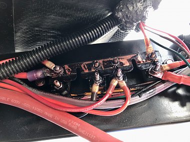
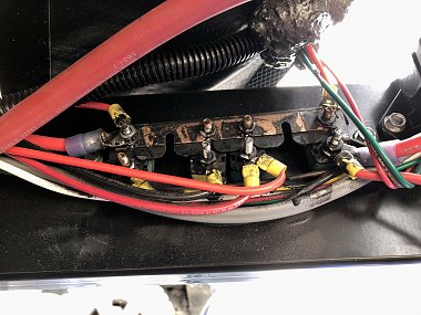
Before I finalized these connections I had to fix the crappy 12v connections on the 4 thermal breakers that are mounted to the frame below the batteries. Winnebago did the same thing I found on my last trailer, Jayco. They used interior grade crimp style ring connectors that offer no protection from the elements, and I already found some green corrosion starting on some exposed wires. They tried to protect the wires with some black spray coating, but that isnt good enough to get into the front and rear of the crimp section of a connector. Heat shrink and/or marine grade crimp connectors are better, and thats what I did on every connection except the one red 6awg connection at the top of the furthest back thermal breaker. That wire had no slack. So, I couldnt cut the connector off and replace it. I just treated it best I could against corrosion, and spray it along with all other connections with battery contact sealant. Then I reinstalled the red rubber covers over each breaker that slide over the two threaded posts. I even replaced the ring connectors on the white 6awg negative lead running between the passenger side battery and the frame. All 6awg & 1/0 connectors I used were heavy with sealed ends by the ring, and I used a heavy crimp tool that I double crimped all the connectors. The last 12v connection I did was a 12awg ground wire from the inverter to the frame. Every connection was to bare metal. Some on the frame I had to make bare, and all received a coating of a corrosion resistive grease designed for electrical connections. Straight forward on the romex. Drilled a hole in the Prepped for Inverter cover, ran the romex up and then across the top, and ran individual wires with spade connectors on the end down and onto the inverters 115v terminal block.
This what the 12v thermal breakers looked like after I removed the red rubber covers.
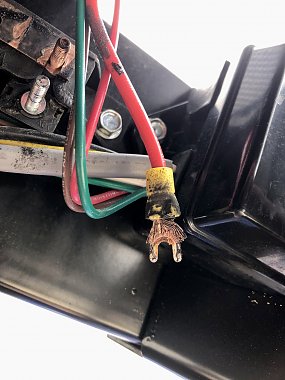
This is how the one original spade connector looked (the rest were ring connectors), and this one connects to the solar panel.
1/0 black - cable in the back through a square hole existing in the frame, and 12awg ground cable right above that white zip tie through a new hole.
I installed the inverter on a 3/8 piece of plywood that I painted. Countersunk screws were run through the back for the inverter and circuit breaker mounting, and lock washers, nylon locking nuts, and/or double-nuts were used to hold things in place. The sheet of wood was cut so it was a snug fit between the floor and the wood cross member above it. This means the vertical weight is controlled by mounting screws and the firm fit. A few more screws through the plywood were added after I took the pictures.
Happy with the install. Mounted up on a bulkhead keeps the storage room in the pass through intact, and I should keep the cooling fans in the inverter clear to do their job. Only thing left is to decide on where we want the inverter remote located inside the trailer, and then run the remote cable in there. The cable is plenty long. I just dont want to cut a hole for flush mounting the remote until I thoroughly think this through. Leading location is the counter next to the bed right under the cabinet. I think putting it into that counter close to the outside wall would give easy access whether the bed was up or down without being in the way.
__________________
Mike, retired Coast Guard
2024 Winnebago Micro Minnie 2108DS
2014 F350 Lariat CCLB 6.7L & 2010 Shelby GT500
|
|
|
|
|
04-01-2024, 08:32 AM
|
#3
|
|
Winnebago Master
Join Date: Nov 2018
Location: Pflugerville/Austin, Tx
Posts: 7,582
|
It looks like you have a good handle on several points and did a lot of good to head off trouble when possible!
So with your recent experience and knowing how much it may help when trouble does come around, I have a question that I've never gotten a good answer on???
Does the trailer group get the same wire ID treatment that the motorized gets? Do the wires get ID's stamped on them, so we can use the ID chart for small wires and depend on ID of some sort for the larger?
I don't see any black Romex listed here, so it may not be used in the trailer group but not having any trailers, I've wonder before referring people to this info, which is often meant for other than trailers:
https://www.winnebago.com/Files/File...agram/Help.pdf
Do you see ID on wires or left to WANDER and wonder? Lots of help in the online drawings for motorhomes but very little for trailer help!
__________________
Richard
Why no RV year, make and floorplan on MY signature as we suggest for others?
I currently DO NOT have one! 
|
|
|
|
|
04-01-2024, 11:53 AM
|
#4
|
|
Winnebago Owner
Join Date: Oct 2020
Location: Asheville, NC
Posts: 1,674
|
No wire ID that I’ve seen.
Routing inverter remote panel would probably be easiest going up through the bedside cabinet up along the corner of bulkhead and sidewall, then up to top of shirt closet. The wire is probably RJ11/21 so it has some shielding, and could be stapled to the wall. but you could always run it through a loom or 1/2” pvc elec conduit. It’s gray, so it would kinda blend in, if you don’t want it exposed. That way, no staples. I ran mine through the same floor hole I made for the ac cables, and used loom to protect it, and zip ties.
Winnebago TT owners are orphans. Surprised WBGO bother to do this prep. I’m guessing they saw the photos from @Fred2106 and me on how to do it, and thought it would be a low cost thing to do during the build. They never do anything on their own unless prompted by owners, with the possible exception of FLX. Which I think is more of an experiment before rolling it out to motorized division.
__________________
Jim. Former, 2021b Micro Minnie 2108DS
Medically grounded, but still lurking the Micro Minnie Discussions
|
|
|
|
|
04-01-2024, 08:49 PM
|
#5
|
|
Winnebago Camper
Join Date: Dec 2023
Posts: 23
|
Quote:
Originally Posted by Morich

It looks like you have a good handle on several points and did a lot of good to head off trouble when possible!
So with your recent experience and knowing how much it may help when trouble does come around, I have a question that I've never gotten a good answer on???
Does the trailer group get the same wire ID treatment that the motorized gets? Do the wires get ID's stamped on them, so we can use the ID chart for small wires and depend on ID of some sort for the larger?
I don't see any black Romex listed here, so it may not be used in the trailer group but not having any trailers, I've wonder before referring people to this info, which is often meant for other than trailers:
https://www.winnebago.com/Files/File...agram/Help.pdf
Do you see ID on wires or left to WANDER and wonder? Lots of help in the online drawings for motorhomes but very little for trailer help! |
No wire IDs on any wire or cable. Research and investigation required.
|
|
|
|
|
04-10-2024, 12:47 PM
|
#6
|
|
Winnebago Camper
Join Date: Apr 2024
Posts: 15
|
Quote:
Originally Posted by IdahoHunter
I called and got a very helpful lady who sent me the drawings I initially thought I needed. I asked for a couple more drawings, and got them right away.
|
Thanks for the info. Are you able to also post the drawings that were sent to you?
|
|
|
|
|
04-10-2024, 04:52 PM
|
#7
|
|
Winnebago Camper
Join Date: Dec 2023
Posts: 23
|
Here's what I got including the drawings for 12v wiring, the 110v wiring, other drawings unrelated to the inverter install, and the 2023 Manual (which is all they have so far....no 2024 manual  ).
__________________
Mike, retired Coast Guard
2024 Winnebago Micro Minnie 2108DS
2014 F350 Lariat CCLB 6.7L & 2010 Shelby GT500
|
|
|
|
|
04-10-2024, 05:17 PM
|
#8
|
|
Winnebago Camper
Join Date: Apr 2024
Posts: 15
|
[QUOTE=IdahoHunter;3951123}...and the 2023 Manual (which is all they have so far....no 2024 manual ).[/QUOTE]
You are absolute gold - Thank You (from Twin btw)
I didn't get a overall unit manual either. For such a fairly complicated item that's just.. weird. 
Did you attach a 2023 manual?
|
|
|
|
|
04-10-2024, 05:22 PM
|
#9
|
|
Winnebago Camper
Join Date: Dec 2023
Posts: 23
|
Quote:
Originally Posted by Dashunde
You are absolute gold - Thank You (from Twin btw)
I didn't get a overall unit manual either. For such a fairly complicated item that's just.. weird.
Did you attach a 2023 manual? |
Hmmm, I thought I did. I selected it for upload. Must have done something wrong. Oh, just tried again, and it exceeds the 3Mb size limit for a pdf upload. The manual is 8.9Mb. Sorry.
__________________
Mike, retired Coast Guard
2024 Winnebago Micro Minnie 2108DS
2014 F350 Lariat CCLB 6.7L & 2010 Shelby GT500
|
|
|
|
|
04-22-2024, 04:08 PM
|
#10
|
|
Winnebago Camper
Join Date: Apr 2024
Posts: 15
|
I looked over the inverterprep.pdf and it shows the loop being cut and both ends being connected to a Xantrex inverter. The Xantrex is a auto-switching unit that restores the original loop when its off or shore power is detected (I assume).
So what I haven't figured out yet with your single connection Renogy is how the converter powers your 110v plugs now that your outlet's direct connection to the converter/shore power is cut/capped.
What did I miss?
Also, with the factory loop.. is the microwave/oven powered by it too?
I don't care too much about the 110v outlets except maybe for a coffee maker and the TV... If I spend on this I'd be hoping to get a minute or two out of the microwave (not 15 minutes baking a pizza, just reheating a leftover)
As for the TV.. I'm thinking about replacing it with a 12v unit anyway, which brings up the next question - Is there 12v in the cabinet above the TV already?
|
|
|
|
|
04-23-2024, 07:36 AM
|
#11
|
|
Winnebago Camper
Join Date: Dec 2023
Posts: 23
|
Quote:
Originally Posted by Dashunde
I looked over the inverterprep.pdf and it shows the loop being cut and both ends being connected to a Xantrex inverter. The Xantrex is a auto-switching unit that restores the original loop when its off or shore power is detected (I assume).
So what I haven't figured out yet with your single connection Renogy is how the converter powers your 110v plugs now that your outlet's direct connection to the converter/shore power is cut/capped.
What did I miss?
Also, with the factory loop.. is the microwave/oven powered by it too?
I don't care too much about the 110v outlets except maybe for a coffee maker and the TV... If I spend on this I'd be hoping to get a minute or two out of the microwave (not 15 minutes baking a pizza, just reheating a leftover)
As for the TV.. I'm thinking about replacing it with a 12v unit anyway, which brings up the next question - Is there 12v in the cabinet above the TV already?
|
The 110v outlets are fed directly from the inverter. When the romex loop in the pass-through is cut, it leaves two separate runs into the trailer. Both runs come up through the floor under the sink. One run goes to the breaker panel, and the other goes to the outlets (via the first one inside the door). The run to the outlets is connected to the Renogy output, which makes all the outlets live provided I have the inverter turned on. The 2nd run to the breaker panel is capped and not used now. The breaker marked for the outlets is turned off, and the other end in the pass-through is capped with wire nuts and taped. However, that run could be re-purposed to route inverter power to the oven or tv by connecting the other end to the inverter and relocating the breaker end to safely provide power to either the tv or oven. That would need to be done separate from shore power.
I don't normally watch tv while in the mountains, but there might be times when the oven would come in handy. Not sure about that change yet. It would certainly sap the batteries some.
I haven't looked into the availability of 12v in the cabinet above the tv. However, the radio runs off 12v, but I don't know the capacity of the wiring to the radio.
__________________
Mike, retired Coast Guard
2024 Winnebago Micro Minnie 2108DS
2014 F350 Lariat CCLB 6.7L & 2010 Shelby GT500
|
|
|
|
|
04-23-2024, 09:07 AM
|
#12
|
|
Winnebago Camper
Join Date: Apr 2024
Posts: 15
|
Quote:
Originally Posted by IdahoHunter
The 110v outlets are fed directly from the inverter.
|
Your 110v outlets are fed from the inverter only? Meaning, when connected to shore power your "inverter prepped" outlets are inoperative? Is that correct?
I'm trying to figure out if you somehow managed to use a $250 Renology inverter and managed to keep those 110v outlets alive on shore power too?
|
|
|
|
|
04-23-2024, 09:20 AM
|
#13
|
|
Winnebago Camper
Join Date: Dec 2023
Posts: 23
|
Quote:
Originally Posted by Dashunde
Your 110v outlets are fed from the inverter only? Meaning, when connected to shore power your "inverter prepped" outlets are inoperative? Is that correct?
I'm trying to figure out if you somehow managed to use a $250 Renology inverter and managed to keep those 110v outlets alive on shore power too?
|
As long as the inverter is on, those outlets will be live. When on shore power, the batteries are being charged by the trailer's converter, and you just leave the inverter on. Put another way, the outlets will ALWAYS be live as long as you have the inverter running. The inverter doesn't stop working because you plug into shore power, which is why you need to have the inverter's 115v power separate from the shore power's 115v.
__________________
Mike, retired Coast Guard
2024 Winnebago Micro Minnie 2108DS
2014 F350 Lariat CCLB 6.7L & 2010 Shelby GT500
|
|
|
|
|
04-23-2024, 09:48 AM
|
#14
|
|
Winnebago Camper
Join Date: Apr 2024
Posts: 15
|
Ohhh.. ok. Now I get it. lol
So long as the load on the inverter doesn't exceed the converters ability to recharge the batteries you're not going to run out of power.
If you had it to do over again, would you use the Renology again, or perhaps spend a bit more on the auto-switching Xantrex to take the recharging load off of the OEM converter while also maintaining original wattage on shore power?
My TV outlet is on the inverter loop, so I'll be sticking with 110v there and adding a DVD player for late night/bad weather use, I'll run a coffee maker of some kind, and the wife will pull 1800 watts (at least) with her hair drier. Plus whatever my daughter plugs in.
I might be better off with an auto-switching option that reestablishes the shore power loop?
|
|
|
|
|
04-23-2024, 09:22 PM
|
#15
|
|
Winnebago Camper
Join Date: Dec 2023
Posts: 23
|
Quote:
Originally Posted by Dashunde
Ohhh.. ok. Now I get it. lol
So long as the load on the inverter doesn't exceed the converters ability to recharge the batteries you're not going to run out of power.
If you had it to do over again, would you use the Renology again, or perhaps spend a bit more on the auto-switching Xantrex to take the recharging load off of the OEM converter while also maintaining original wattage on shore power?
My TV outlet is on the inverter loop, so I'll be sticking with 110v there and adding a DVD player for late night/bad weather use, I'll run a coffee maker of some kind, and the wife will pull 1800 watts (at least) with her hair drier. Plus whatever my daughter plugs in.
I might be better off with an auto-switching option that reestablishes the shore power loop?
|
Too early to answer that question since I just finished the install and haven't used it since then. Right now the dealership has had it for 10 days just to replace a warped cupboard door (which the replacement is in their hands), a speaker, and get three ceiling a/c vents to rotate. Not impressed with how long they are taking for a 1 hour job!
I will say that I like to keep the important stuff like power pretty simple. KISS. I've got a technical background and a degree in tech, but stuff fails. I don't want to infuse my trailer with too many features that may increase the likelihood of something failing. Then if something fails, I've got to craft a work around while in the mountains. I do all of my single camping up in the mountains. No hookups. My wife and I will do more camping together with this trailer, but we'll probably do 50/50 boon docking and park camping with hookups. I have a 100w briefcase solar panel setup that I can plug in to run parallel with the roof panels, which should help recharge the two AGM batteries. We both use CPAP machines, which is why feeding the outlets from the Renogy is important. Morning will come with the battery level down a bit.
I have nothing that I envision ever coming close to over-tasking the Renogy. I'll hook up the remote for the inverter so I can turn it on/off from inside, but I imagine it will be left on a lot because it doesn't kick in until something demands some current. My hope is that it's a transparent power source, and even if we do some camping with hookups, the CPAPs will be the heaviest load for the inverter due to the length of time they'll be used.
__________________
Mike, retired Coast Guard
2024 Winnebago Micro Minnie 2108DS
2014 F350 Lariat CCLB 6.7L & 2010 Shelby GT500
|
|
|
|
|
|
Currently Active Users Viewing This Thread: 1 (0 members and 1 guests)
|
|
|
 Posting Rules
|
You may not post new threads
You may not post replies
You may not post attachments
You may not edit your posts
HTML code is Off
|
|
|
|
 » Recent Discussions
 |
|
|
|
|
|
|
|
|
|
|
|
|
|
|
|
|
|
|
|
|
|
|
|
|
|


 Linear Mode

