 |
|
 05-24-2023, 05:17 PM
|
#1
|
|
Winnebago Owner
Join Date: Nov 2022
Posts: 63
|
Schwintek Slide Issue 2014 Itasca Suncruiser 37F
2014 Itasca Suncruiser 37F with a Schwintek Super slide 28 feet.
I noticed Denny49 posted on May 20Th about his slide issue. Mine is somewhat similar with a twist. My 28 foot super slide goes out about 1-3 inches, then stops. Hit the retract button to bring back in an inch and stop. Hit the out an it goes 1-3 inches and stops. Repeat until slide is all the way out, which is 19.5 inches.
I have cleaned and lubricated per directions, I have reset the controller twice. The motors do not appear to be under any stress. They just stop and you have to go the opposite direction before you can proceed, in either out or in. And sometimes you have to press the control switch twice to activate movement. I am able to finally open and close by moving the slide back and forth, but I don't want to burn up or destroy anything in the process either. Someone mentioned that the rocker switch may need replaced. Could a bad rocker switch cause this type of issue? Not contacting the wires correctly.
I am home for two-three weeks before next trip (month long). Is there any other insight before I end up taking it to a shop and pay $135/hour?
Thanks for positive feedback and I hope I have enough information above.
|

|

|
|
05-25-2023, 08:21 AM
|
#2
|
|
Winnebago Master
Join Date: Nov 2018
Location: Pflugerville/Austin, Tx
Posts: 7,526
|
Looking at this brngs a few questions first!!
Sorry about the slow process but it leads to better answers!
When moving in or out, does the slide seem to stay even left to right as if both motors are working at the same time? If so this would seem to indicate it is not a problem involing only one end, left or right but something common to both. If we go with that idea we can move away from one motor, one set of wires to that motor or most things past the controller!
So what we have left is more likely, the actuator switch or wiring from that switch to the controller as something that is going open and then working again for a bit before going open again??
You may have nailed the problem but it needs some looking/ testing of the switch to try to sort the better idea. This is a switch which is somewhat complex in that it has six wires and six contacts inside. More contacts in smaller space makes it more likely to go bad but the way it mounts can often make it tough to get out of the wall!
Have you worked with this type switch that has "fingers"
or spring type clamps which press in as it is pushed into a mounting hole and then spring out to hold it in?
Not hard to test the switch but getting it out can be a trick! They make it easy to build but hard to get apart if we can't reach the back side to squeeze the fingers in!
This is not the correct switch (too many contacts shown!)but to maybe lead to how to get it out?
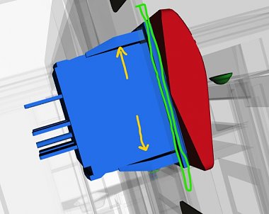
If the green lines are a retangle hole cut in the wall, they slide it in the ramps make the fingers compress until they get fully in the wall and then bring back out to clamp the switch in the hole. To get it out without tearing the wall, we need to compress both top and bottom fingers so they will pull out!
Easy enough if we can reach in behind but can be tough to do from the front.
Maybe others know of a good way but I've never found it!!
But once you get the switch out, it can be fairly easy to test. If you happen to have model railroad experience you will recognize this as a "reversing switch"
for the layout!! 
Here it is a reversing switch for the motors on the slide!
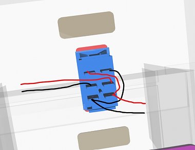
You should be able to spot the wire ID on the wire labels.
Use this chart to ID each wire if needed:
https://www.winnebago.com/Files/File...ical_guide.pdf
There should be two wires for 12VDC supplied from switch to controller as I drew going left.
There should be two wires from the battery supply and ground that I've drawn coming in at the right. These may go to the top or bottom set of lugs first, so don't let that throw you as they then are connected but in reverse to the outer lugs on the other end.
The idea is the center two lugs connect to either the top two or the bottom two as we push the switch. If we push it up, the power polarity is one way but pushed down it is reversed as it goes out to the left to the controller and motors.
I've drawn them red and black but I don't know which will be battery and which ground, so don't use my colors as a guide, just to show the idea!!
You "might" be lucky and find one of these wires has a loose push on connector or broken wire but I really suspect you will find the contacts inside for the center lugs is burned and not always making good contact when the switch is pushed.
You may be able to check this if you can push the switch only part way to make the contacts land in a slightly different spot than if fully pushed??
If you have a set of small jumpers, clipping the jumpers on one center and then on the incoming power or ground to bridge around the switch may make it certain that the switch is the problem.
But you can also blow the fuse if you fumble this, so your choice on the value versus the hazard! 
I may have told you way more than needed but I'd rather waste your time reading than leave you guessing too far. Sorry about that but we never know what the other folks might already have done! 
__________________
Richard
Why no RV year, make and floorplan on MY signature as we suggest for others?
I currently DO NOT have one!
|
|
|
|
|
05-25-2023, 09:21 AM
|
#3
|
|
Site Team
Join Date: Sep 2009
Location: Spring Branch, TX
Posts: 7,830
|
Slide controllers do fail and it's possible that yours has done so.
Sometimes a phone call to LCI Support will go a long way in diagnosing and maybe even solving an issue.
Here's their online support page for Schwintec and PowerGear "In-Wall" systems:
https://support.lci1.com/in-wall-slide-out
Customer Service
[email protected]
432-LIPPERT (432-547-7378)
__________________
2017 Winnebago Adventurer 37F
2016 Lincoln MKX Toad
|
|
|
|
|
05-26-2023, 12:37 PM
|
#4
|
|
Winnebago Owner
Join Date: Nov 2022
Posts: 63
|
Thank You, Morich and creativepart. I was able to remove the rocker switch pretty easily. I am now waiting on a new one. If this does not work, I will replace the controller in the compartment bay. I appreciate the insight from both of you. It helps with diagrams and part locations.
|
|
|
|
|
05-26-2023, 01:06 PM
|
#5
|
|
Site Team
Join Date: Sep 2009
Location: Spring Branch, TX
Posts: 7,830
|
I don't know if it's possible, but let me make the suggestion and you see what you think.
If you locate the two slide controllers, look at the part numbers and see if they are the same. It's possible they are. And, if they are, you could try removing the working slide's controller and plugging it into the cabling on the non-working slide's controller.
This way you could test to see if it is the controller or not.
Heck, I guess you could try the same with the switches. Maybe they are the same too? Who knows?
Buying parts without knowing whether they are the issue or not is one way to go. But, further testing to effect more focused troubleshooting can be helpful and cheaper.
__________________
2017 Winnebago Adventurer 37F
2016 Lincoln MKX Toad
|
|
|
|
|
05-26-2023, 07:37 PM
|
#6
|
|
Winnebago Master
Join Date: Nov 2018
Location: Pflugerville/Austin, Tx
Posts: 7,526
|
Since you've done the "hard " part and got the switch out, now is a good time to test the switch!
Do you have a seperate key type switch to turn on when you want to move the slides?
If you leave that switch off while putting a couple wires on the switch and then turn the key, the slide should try to move in or out.
On this drawing, I numbered the connections so we can talk about them. The numbers on the switch may be totally different and this is just for ease of describing them.

When we push this type switch, it makes it connect two different sets of wires together. Pushed up wire 1 is connected to wire 2 and at the same time wire 4 is connected to 5.
Then if we push the switch down, it connects 1 to 3 and 4 to 6!
We wired 2/3 and 5/6 reversed for the power coming in. The power going out toward the slide is reversed when we push the switch one way or the other. One way makes it move in, the other out!
If you tie any kind of small wire between 1 and 2 and another wire between 4 and 5, that is what the switch is trying to do inside. But if we put the wire on, we know it is there, for sure, even if the switch is bad inside!
So with the wires on, if we turn the key switch on to put power to them, the wires should make the slide move. I can't say which way but it should be obvious that it is trying, even if all the way in. Just don't leave the key on so long it gets the motors hot enough to burn out!!! They are made to let us overrun a few seconds or so past closed but just not 5 minutes, etc.
Warning! If you are next to something close like your car, really be ready to turnh that key off because if it starts moving it may try to keep moving until it breaks something!! 
If you have somebody to hold the switch steady, it can be quicker to use some metal tool like small pliers to short/ connect 1 to 2 and 4 to 3 at the same time, just long enough to see the slide try to move.
Since I play with wires so much, I have a set of small jumper wires with clips on each end to hook on things like this.
This is really getting down into the bushes on searching, so don't let me talk you into anything you are not comfortable doing as it can blow the slide fuse, etc if you happen to hit the wrong two while the key switch is on. 
__________________
Richard
Why no RV year, make and floorplan on MY signature as we suggest for others?
I currently DO NOT have one!
|
|
|
|
|
05-26-2023, 10:09 PM
|
#7
|
|
Winnebago Master
Join Date: Aug 2008
Location: Texas
Posts: 1,666
|
Amazon has the Schwintek slide controller.
I believe it was mentioned that the slides have to go out evenly and not more than a 2" difference (which is to much in my opinion) between sides.
Also, the calibrate the motors it is necessary to hold the slide switch in the "IN," or "OUT" position for a minimum of 5 seconds after the slide stops. Many times you will hear one motor still whirring.
You can push the reset button on the controller (Instructions on controller) and by-pass all physical controls except the push button. When by-passing the controls there is a risk if something is seriously wrong with alignment (one side going further than the other). Those motors are extremely powerful and can tear things up.
It is possible that it is a bad motor.
__________________
Wayne MSGT USMC (Ret) & Earlene (CinCHouse)
2015 Winnebago Tour 42QD - 2020 Lincoln Nautilus Reserve (TOAD)
(RVM-14) It is what it is, and then it is what you make of it.
|
|
|
|
|
05-27-2023, 06:36 AM
|
#8
|
|
Winnie-Wise
Join Date: Oct 2018
Posts: 356
|
My 2012 Itasca Suncruiser 37F has electric slide locks. If the shafts on one or both of the locks is stripped it may cause the slide to become cocked and refuse to move. After paying $$$ to have both locks replaces, I quit using them and cut a couple 2X4s to length and lay it on top of the slide to lock it in. I stapled a long red ribbon onto the 2X4, so I don't forget it is there.
|
|
|
|
|
05-31-2023, 05:35 PM
|
#9
|
|
Winnebago Camper
Join Date: Nov 2020
Posts: 16
|
Drivers slide out
Quote:
Originally Posted by fyreplug

2014 Itasca Suncruiser 37F with a Schwintek Super slide 28 feet.
I noticed Denny49 posted on May 20Th about his slide issue. Mine is somewhat similar with a twist. My 28 foot super slide goes out about 1-3 inches, then stops. Hit the retract button to bring back in an inch and stop. Hit the out an it goes 1-3 inches and stops. Repeat until slide is all the way out, which is 19.5 inches.
I have cleaned and lubricated per directions, I have reset the controller twice. The motors do not appear to be under any stress. They just stop and you have to go the opposite direction before you can proceed, in either out or in. And sometimes you have to press the control switch twice to activate movement. I am able to finally open and close by moving the slide back and forth, but I don't want to burn up or destroy anything in the process either. Someone mentioned that the rocker switch may need replaced. Could a bad rocker switch cause this type of issue? Not contacting the wires correctly.
I am home for two-three weeks before next trip (month long). Is there any other insight before I end up taking it to a shop and pay $135/hour?
Thanks for positive feedback and I hope I have enough information above.
|
Tech stopped by today and found one motor seized up. Rudy residue on top of the front motor. Everything else tested ok. Bit the bullet and ordered a replacement motor. Hope to have fixed by the weekend. Not a cheap service call but I had no idea how to address the issue. Good luck on yours.
|
|
|
|
|
05-31-2023, 05:47 PM
|
#10
|
|
Winnebago Master
Join Date: Nov 2018
Location: Pflugerville/Austin, Tx
Posts: 7,526
|
On the point of it being a motor or not, I feel there seems to be evidence that it is NOT a motro. When it goes out but only a few inches and then stops but can eventually get it all the way out, I assume that both motors are moving thier end but both lose power before getting fully extended.
In my mind, that puts in back intot he parts which feed power to both sides.
But I have to admit that I did not question the OP if the slide is actually going out even or not, so maybe some more questions need to be asked to avoid the wrong idea.
We are often not as good at communicating as we think!
__________________
Richard
Why no RV year, make and floorplan on MY signature as we suggest for others?
I currently DO NOT have one!
|
|
|
|
|
05-31-2023, 11:40 PM
|
#11
|
|
Winnie-Wise
Join Date: Nov 2014
Location: Washington State
Posts: 297
|
Morich:
Lurking here. Wonderfully educational and clear. Thank You!
__________________
_______________________
2014 Itasca 27n
|
|
|
|
|
06-01-2023, 05:51 AM
|
#12
|
|
Winnebago Owner
Join Date: Sep 2017
Posts: 66
|
Try retiming the Schwintek slide: https://store.lci1.com/blog/retiming-schwintek-slide-out-preventing-syncing-issues
Larry 2014 Reyo P
|
|
|
|
|
06-01-2023, 09:35 AM
|
#13
|
|
Winnebago Master
Join Date: Nov 2018
Location: Pflugerville/Austin, Tx
Posts: 7,526
|
Quote:
Originally Posted by danhannah
Morich:
Lurking here. Wonderfully educational and clear. Thank You!
|
Thanks for the thought! Now if I could learn to type OR proofread before sending. I lost typeing when in the service and tyeping code and then regained what was marginal to begin with!
Now I set here and often get called just as I "almost" have something ready, so send without corrections and it looks like a five year old did it!
The idea I go by is like if we had two lights on one switch. If one light goes out, we look at that light but if BOTH lights go out, it leans more toward the items common to both like switch or wiring, etc.
__________________
Richard
Why no RV year, make and floorplan on MY signature as we suggest for others?
I currently DO NOT have one!
|
|
|
|
|
06-01-2023, 01:38 PM
|
#14
|
|
Winnie-Wise
Join Date: Apr 2016
Posts: 286
|
He has other videos on the subject< I'd tend to listen to him.
__________________
2015 Itasca Sunstar 35F
|
|
|
|
|
06-01-2023, 06:20 PM
|
#15
|
|
Winnebago Watcher
Join Date: Nov 2018
Posts: 2
|
I have a 2014 Winn Forza 38R with a long slide on passenger side.
In 2019 I was at the North Rim of the Grand Canyon and that slide was stuck all the way out, but crooked. The apparatus was Schwintek. Winnebago soon learned that the Schwintek system was not suited to long slides and stopped using it on this model in 2015 or 2016. After numerous conversations with the factory, I was told that Winn. had issued an unpublished recall on certain models with long slides using the Schwintek system. In fact, in 2019 I learned they had a shop set up in Iowa to make the repair at the factory. Winnebago worked with me and LCI to resolve the issue. Since I could not get back to Iowa, I was able to schedule the repair in San Diego and Winnebago shipped the parts directly to the dealer there. It was a one day repair. There was a minor mixup on the controller, but once I had the correct controller in place, it has worked well ever since. The newer Winnebagos I have seen with long slides now have that system..............Power Gear, I believe is the name of it, also by LCI. Talk to the manager in the small jobs shop at Winnebago...............no one else at the factory was able to help.
|
|
|
|
|
06-01-2023, 06:27 PM
|
#16
|
|
Winnebago Watcher
Join Date: Nov 2018
Posts: 2
|
Check out my post at 8:20
Yours is doing what mine did initially with the Schwintek system.
Winnebago changed it out with the Power Gear system and it works great.
A long slide is a problem with the Schwintek system.
|
|
|
|
|
06-02-2023, 07:43 AM
|
#17
|
|
Winnebago Owner
Join Date: Nov 2022
Posts: 63
|
Update -
LCI support was useless. They could not diagnose the problem and when asked about a replacement controller they had no part number to match mine. They said call Winnebago. Called Winnebago tech support and the guy said it was almost certain I needed a new controller because the LED lights lit up like Christmas tree when the switch was pushed ( either extend or retract). Also both motors work together and stop together - no difference. Only will go 1-2 inches at a time.
I had to call Mobility RV. Inc ( Winnebago parts distribution) which is 15 miles down the road from Winnebago itself. They had to find a match for the controller because LCI no longer makes that particular part number anymore. I am now waiting on the new controller which should be here next Wednesday. I leave the following Monday. More to come next week.
|
|
|
|
|
06-02-2023, 11:05 AM
|
#18
|
|
Winnie-Wise
Join Date: Nov 2014
Location: Washington State
Posts: 297
|
Feeling your pain...
__________________
_______________________
2014 Itasca 27n
|
|
|
|
|
06-08-2023, 02:15 PM
|
#19
|
|
Winnebago Owner
Join Date: Nov 2022
Posts: 63
|
After installing new controller, I am now getting a motor 1 - wire short between controller and motor. I have now ordered a new wiring harness. I was told by Winnebago Tech support that I could get to the channel for the wiring harness behind the bulb seal below the slide. That is all metal behind the seal.
Has anyone pulled a new wiring harness for the super slide? Remember - 2014 Itasca Suncruiser 37F. Approximately a 28 foot slide.The controller is in the middle of the slide underneath in the storage compartment. I believe I need to take the harness cover off at end of slide inside the coach and pull the old cable out, with new attached, from the floor. ????
Any help from creativepart, Morich, or any others is greatly appreciated.
|
|
|
|
|
06-25-2023, 09:18 AM
|
#20
|
|
Winnebago Owner
Join Date: Nov 2022
Posts: 63
|
Latest Update:
We have been at the Winnebago Factory Service Center in Forest City, IA since Wednesday 21 June. The people here are fantastic, and we have gotten a couple things fixed, but the super slide on the driver's side is the big issue. Basically, there were more issues to the slide than we anticipated.
Good news is they are able to fix it, just taking time. Rebuilding the whole Schwintek slide mechanism and replacing just about the whole system. I could have opted for the power gear conversion however it would not have been completed until after 8 July. Cannot wait that long.
Because of it taking more time and parts, the service manager who we are working with stated he would keep to the price given us. That's commitment and service. We do get to stay in the parking lot (along with about six other motorhomes) free of charge with at least power. No water or sewer.
So far very pleased with the people at the service center and highly recommend anyone with a Winnebago to come here for fixes, if at all possible, should the repair be above your ability. I found out it was much more than I expected. So glad I made the choice to come.
More to follow.
|
|
|
|
|
|
|
Currently Active Users Viewing This Thread: 1 (0 members and 1 guests)
|
|
|
 Posting Rules
|
You may not post new threads
You may not post replies
You may not post attachments
You may not edit your posts
HTML code is Off
|
|
|
|
 » Recent Discussions
 |
|
|
|
|
|
|
|
|
|
|
|
|
|
|
|
|
|
|
|
|
|
|
|
|
|


 Linear Mode

