 |
 04-02-2023, 06:15 AM
|
#1
|
|
Winnebago Owner
Join Date: Dec 2016
Posts: 63
|
Battery Isolation Manager 2016 Vista LX 27N
The Precision Circuit part number 10021-000 for my rig is of course no longer available. Winnebago parts numbers to replace are:
332068-01-000 new style battery isolation manager
332004-01-02B bracket
332005-01-02B bracket
Anyone out there installed these? Looked for a video on line but cant find one.
My rig has a small door on the drivers side with circuit breakers and the BMI is located behind the circuit breakers. I have skills but just wondering if anyone out there can give me a tip or two before I dig into the spaghetti of wires behind the circuit breakers. Honestly I was surprised when I received the parts. The 332004-01-02B bracket is not what I expected to replace.
Anyway, any tips from someone who has replaced these parts would be appreciated.
Thanks
__________________
Martin & Michelle and our dog Blue, Paradise, CA.
2016 Winnebago Vista LX 27N, Sumo Springs, rear track bar, Safe-T- Steer, Dish
2017 Equinox Premier AWD V6, Blue OX base and bar, SMI Stay and Play Duo
|

|

|
|
04-02-2023, 08:25 AM
|
#2
|
|
Site Team
Join Date: Sep 2009
Location: Spring Branch, TX
Posts: 7,826
|
I don’t have a 2016 Vista LX 27N, but a similar 2017 Adventurer. So, I am sure there are differences, but when I installed my LFP battery bank I disconnected the BIM on my RV. When I first contemplated the work I was very intimidated by the mass of wires, like you. But once I dug into the project every thing made sense and was pretty straightforward.
Basically there are two separate sides; one side is chassis power the other side is house power. In between is the BIM. On my RV there were just two spades, one on each side connected to the BIM. Each spade came out from a power disconnect solenoid again on each side. Once I removed the nuts securing the BIM to the spades I could pull the BIM out enough to see the rest of the connections to the BIM.
The few other connections to the BIM were simple things like a ground wire, an ignition trigger and the aux battery boost switch wire. I’m sure you’ll just connect those like for like on the new BIM.
You must disconnect all power - battery cables, of course, but also shore power and solar panel connections to work on this area. Before working use a volt meter to test everything to insure that nothing is still connected.
If you have a Magnum inverter be sure to disconnect the positive battery cables first as per Magnum’s instructions or you can fry your inverter. I don’t know about other brands of inverters but perhaps you should double check that if you have some other brand.
The point I’m making is, you don’t have to mess too much with any wires but those on the BIM. All the wires on the left and right that attach to the disconnect solenoids are not involved. Just where the solenoid spade connects to the BIM on each side.
As I said, it didn’t make any sense to me until I started to work on it.
__________________
2017 Winnebago Adventurer 37F
2016 Lincoln MKX Toad
|
|
|
|
|
04-02-2023, 08:40 AM
|
#3
|
|
Site Team
Join Date: Sep 2009
Location: Spring Branch, TX
Posts: 7,826
|
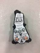
Here are some photos. The last one is of the BIM after I disconnected it from the solenoids you can see in the back of the photo.
In the second photo you can see the two large red cables in the center of the photo. One has a red shrink wrap on it the other has a yellow wrap. Those are the two main chassis and house cables. Those large nuts are holding the spades to the disconnect solenoids on each side. Those nuts are what you remove to free the BIM of the solenoids. Once those are removed you simply remove the BIM’s mounts and pull it out.
__________________
2017 Winnebago Adventurer 37F
2016 Lincoln MKX Toad
|
|
|
|
|
04-02-2023, 08:50 AM
|
#4
|
|
Winnebago Owner
Join Date: Dec 2016
Posts: 63
|
Thanks for the info.
Thats interesting that you left the BIM brain in the circuit. What did you the replace the solenoid with? Maybe I misunderstood. Your pic of the bim and the batt disconnect relays is exactly what I see on my rig. Winnebago sent me two additional brackets that need to be replaced to accommodate the new BMI. Wasn't expecting that.
__________________
Martin & Michelle and our dog Blue, Paradise, CA.
2016 Winnebago Vista LX 27N, Sumo Springs, rear track bar, Safe-T- Steer, Dish
2017 Equinox Premier AWD V6, Blue OX base and bar, SMI Stay and Play Duo
|
|
|
|
|
04-02-2023, 08:51 AM
|
#5
|
|
Site Team
Join Date: Sep 2009
Location: Spring Branch, TX
Posts: 7,826
|
All small yellow wires are 12v positive and white wires are negative. Which is a Winnebago standard configuration.
__________________
2017 Winnebago Adventurer 37F
2016 Lincoln MKX Toad
|
|
|
|
|
04-02-2023, 08:58 AM
|
#6
|
|
Site Team
Join Date: Sep 2009
Location: Spring Branch, TX
Posts: 7,826
|
Quote:
Originally Posted by Park Super

Thanks for the info.
Thats interesting that you left the BIM brain in the circuit. What did you the replace the solenoid with?
|
I didn’t replace anything. My goal was to disconnect the Alternator from the house battery charging circuitry. Since I disconnected those main cables the BIM could no longer connect the house and chassis power together accomplishing my goal. After the BIM was removed I did reconnect those big cables, but directly to each of the disconnect solenoids.
I left the BIM there in case I ever wanted to reconnect it in the future. I had planned on removing the BIM entirely but didn’t see a reason to take that step.
With a volt meter I could test that alternator output was reaching the chassis disconnect but not the house. Just as desired.
With lithium batteries you don’t want the alternator attempting to charge the house bank. I replaced that charging while driving function with a DC2DC charger.
PS. I’d never done anything like this previously. I just dove in head first and took it one obvious step at a time. I didn’t know how to do it until I did it.
__________________
2017 Winnebago Adventurer 37F
2016 Lincoln MKX Toad
|
|
|
|
|
04-02-2023, 09:07 AM
|
#7
|
|
Winnebago Owner
Join Date: Dec 2016
Posts: 63
|
got it
__________________
Martin & Michelle and our dog Blue, Paradise, CA.
2016 Winnebago Vista LX 27N, Sumo Springs, rear track bar, Safe-T- Steer, Dish
2017 Equinox Premier AWD V6, Blue OX base and bar, SMI Stay and Play Duo
|
|
|
|
|
04-02-2023, 09:12 AM
|
#8
|
|
Winnebago Owner
Join Date: Dec 2016
Posts: 63
|
this is what I am going to install
__________________
Martin & Michelle and our dog Blue, Paradise, CA.
2016 Winnebago Vista LX 27N, Sumo Springs, rear track bar, Safe-T- Steer, Dish
2017 Equinox Premier AWD V6, Blue OX base and bar, SMI Stay and Play Duo
|
|
|
|
|
04-02-2023, 09:15 AM
|
#9
|
|
Site Team
Join Date: Sep 2009
Location: Spring Branch, TX
Posts: 7,826
|
Quote:
Originally Posted by Park Super
Winnebago sent me two additional brackets that need to be replaced to accommodate the new BMI. Wasn't expecting that.
|
In the middle photo, those two brass objects in the middle below the BIM are the OEM brackets. They locate the BIM and in turn hold the left and right solenoids in place. Perhaps you can reuse the OEM brackets? Youll find out when you get in there.
__________________
2017 Winnebago Adventurer 37F
2016 Lincoln MKX Toad
|
|
|
|
|
04-02-2023, 09:19 AM
|
#10
|
|
Site Team
Join Date: Sep 2009
Location: Spring Branch, TX
Posts: 7,826
|
Quote:
Originally Posted by Park Super
|
Yes thats the new shape. They make a special Lithium version of that BIM too. I didnt like how it worked and didnt use it.
So you will no doubt need the new mounting brackets since its so different.
__________________
2017 Winnebago Adventurer 37F
2016 Lincoln MKX Toad
|
|
|
|
|
04-02-2023, 09:43 AM
|
#11
|
|
Winnebago Master
Join Date: Nov 2018
Location: Pflugerville/Austin, Tx
Posts: 7,518
|
As a way to preplan and perhaps ease the mind a bit, there are several things online that give some good info. One is that the wires are labeled, so if you spot that, you may not have to worry about where they go or doing a label?
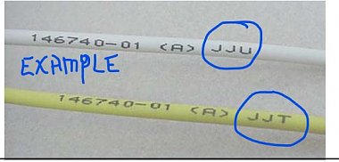
These wire ID can be "decoded" with this list showing where they come from and to:
https://www.winnebago.com/Files/File...ical_guide.pdf
Also this is the drawing of that part of the RV:
https://www.winnebago.com/Files/File...ire_188335.pdf
I think you are looking at what is shown on sheet 2! Note that not all wires are on all RV due to options and whether US or Canada, so just skip any missing?
Note that each wire on the drawing has a label that should match up with the labels on the wires and the list.
There is also a label system for the big battery cables:
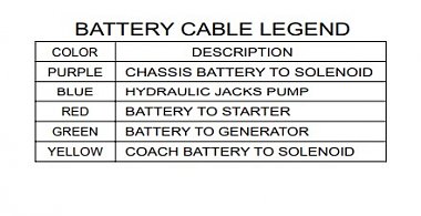
Notice the colors on the battery cables in photo above?
So if the new part is labeled at all well or directions come with it, you should be able to reconnect it wire by wire without too much stress---after figuring how to mount it! 
__________________
Richard
Why no RV year, make and floorplan on MY signature as we suggest for others?
I currently DO NOT have one! 
|

|
|
|
04-02-2023, 10:49 AM
|
#12
|
|
Winnebago Owner
Join Date: Dec 2016
Posts: 63
|
Thank you for your tips. Love that wire decoder keeping that in my files.
__________________
Martin & Michelle and our dog Blue, Paradise, CA.
2016 Winnebago Vista LX 27N, Sumo Springs, rear track bar, Safe-T- Steer, Dish
2017 Equinox Premier AWD V6, Blue OX base and bar, SMI Stay and Play Duo
|
|
|
|
|
04-02-2023, 11:44 AM
|
#13
|
|
Winnebago Master
Join Date: May 2015
Location: Manhattan, Kansas USA
Posts: 1,318
|
Also have a 27N with the Chassis Electrical Box accessed from the door on the driver's side.
I have been into there to connect a DC-DC charger to charge my Lithium Iron Batteries while driving after I disabled the OEM alternator charging.
Yes, there are 3 contactors with the Chassis<>Coach contactor with the BIM on it in the middle in the center BEHIND the Circuit Breaker panel. There are contactors controlled by the Chassis Battery disconnect switch and the Coach Battery disconnect switch on each side.
There are also a couple of in-line fuses and small relays back in there too.
There is a good Chassis Electrical Box drawing on WinnebagoInd.com at least for my 2015 Vista 27N. Other good references are the newest electrical diagram available , which is for a 2013 Vista. And, the Winnebago Wire ID label guide.
= = = = = = = = = = = = = = = = = = = =
When I converted to Lithium Iron Batteries on my Vista 27N in November I went a different way. I continue to use the Winnebago OEM Precision Circuits BIM and Contactor by figuring out a small modification that uses the logic of the BIM to inhibit the BIM and Contactor from connecting the chassis DC (with alternator) to the coach DC (with Lithitum Iron batteries) when the Ignition key is in the ON position.
The BIM works as it always did with the Ignition key in OFF, that way the BIM can keep the chassis battery charged from the Coach DC when there is charging voltage present on the Coach DC and it senses the Chassis battery needs charging.
How?
The BIM has logic that inhibits connecting Coach DC to Chassis DC when there is battery voltage present on both the Gen-Set and Ignition inputs. This is to prevent un-desirable interactions between the AC-DC converter charger and the Alternator trying to charge the same DC system at the same time. It has a GENERATOR input to accomplish this.
So, I modified the wiring to the BIM so that whenever there is 12 volts present on the BIM IGNITION input there is also 12 volts present on the GENERATOR input.
This involves using 2 silicon diodes to keep the IGNITION wire (KE) voltage from backfeeding into the GENERATOR wire (LP).
You can use a Dual Diode module or can make your own from raw diodes. I used a dual diode block (available from Amazon or Etrailer, etc) I had left over from wiring up a towed car.
__________________
Randy - Manhattan, Kansas
2015 Vista 27N
2020 Ford Escape Hybrid
|
|
|
|
|
04-03-2023, 05:52 AM
|
#14
|
|
Winnebago Owner
Join Date: Dec 2016
Posts: 63
|
Thanks Randy, My BIM has failed, and I am keeping my flooded batteries. But interesting how you worked around the lithium charging. Still hoping someone out there has replaced the BIM and installed the new brackets. However, as Creativepart suggests I will dive in as I always do.
__________________
Martin & Michelle and our dog Blue, Paradise, CA.
2016 Winnebago Vista LX 27N, Sumo Springs, rear track bar, Safe-T- Steer, Dish
2017 Equinox Premier AWD V6, Blue OX base and bar, SMI Stay and Play Duo
|
|
|
|
|
04-09-2023, 12:27 PM
|
#15
|
|
Winnebago Owner
Join Date: Dec 2016
Posts: 63
|
In case you all were wondering....... I replaced the BMI and the new brackets today. Took me 3 hours and works wonderful. The old BMI did have an extra wire labeled Gen Set and new BMI had no terminal for this connection. Others on this site mentioned this wire and the solution was to leave it disconnected....so I did and all seems well. Thanks for your suggestions.
__________________
Martin & Michelle and our dog Blue, Paradise, CA.
2016 Winnebago Vista LX 27N, Sumo Springs, rear track bar, Safe-T- Steer, Dish
2017 Equinox Premier AWD V6, Blue OX base and bar, SMI Stay and Play Duo
|
|
|
|
|
|
Currently Active Users Viewing This Thread: 1 (0 members and 1 guests)
|
|
|
 Posting Rules
|
You may not post new threads
You may not post replies
You may not post attachments
You may not edit your posts
HTML code is Off
|
|
|
|
 » Recent Discussions
 |
|
|
|
|
|
|
|
|
|
|
|
|
|
|
|
|
|
|
|
|
|
|
|
|
|


 Linear Mode

