 |
|
 04-19-2023, 11:12 PM
|
#1
|
|
Winnebago Master
Join Date: Nov 2014
Posts: 578
|
Winnebago Circuit Breaker Panel
I have a question as to the orientation of the Electrical Panel in my 2007 Journey 36G.
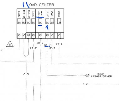
Please see the attached picture. My question is this, in the picture there are 5 double breakers and one single breaker for a total of 6.
Lets number these breaker slots in our head as 1 through 6. Breaker #1 is incoming power from one of the 50A 120v legs of power and Circuit #1 of my basement Air Conditioner. Breaker #2 is the other incoming 50A 120v leg of power and power for Circuit #2 of my basement Air conditioning.
We know that these two breaker positions are not electrically connected and power the A and B legs of power.
Here is the question, can I assume that breaker 3, and 5 are fed from the incoming power from Breaker 1, and that breakers 4 and 6 are fed from the incoming power from breaker 2?
I know that some RV AC Breaker panels have the main breakers in the center and everything on the left is fed from the left main breaker and everything on the right is fed from the right main breaker on the right side.
Mine appears to me at first glance to be oriented like a residential breaker panel.
I will at some point check this physically, but wondered what the smarter than me folk thought.
I also see two blank spots to the right, but didn't know if the buss bar extended to provide a connection point for two more breakers, 7 and 8. Does anyone know?
__________________
2007 Winnebago Journey 36SG and 2013 Honda CRV Toad
e-Trailer XHD Towbar (Demco) Blue Ox baseplate, SMI Stay N Play brakes
|

|

|
|
04-20-2023, 04:52 AM
|
#2
|
|
Just Trying to Help
Join Date: Aug 2015
Posts: 526
|
Tim-
Wiring diagrams for a 2007 36G are here. For a 2007 36SG, here.
By your picture, it looks as if you have a 36SG, so the relevant diagrams are:
110 Volt Load Center/Auto Transfer Switch and
Body, 110 Volt Wiring Diagram
These may answer some of your questions.
Water heater and refrigerator are the two signals for the EMS. This implies they are on different 50A legs. I could be incorrect.
There doesn't appear to be space for more breakers on the buses. You could use a dual breaker in place of the single for the water heater, assuming the load center can take the load. This would add a breaker. Use a 15-20 or 20-15 as needed to keep the water heater on the same leg.
Finally, to open up a breaker space you may be able to add an Intellitec Automatic Energy Selector Switch (AESS), link here. I added one on my coach, to share the water heater and microwave circuits so I could dedicate a breaker to the washer/dryer. If you added one you'd have to noodle through its wiring, considering the EMS.
__________________
Mark
2008 Holiday Rambler Admiral 30PDD (Ford F-53 chassis)
2009 Honda Fit Sport
|
|
|
|
|
04-20-2023, 06:13 AM
|
#3
|
|
Winnebago Master
Join Date: Nov 2014
Posts: 578
|
Reason for my questions is that I am wanting to eventually install LiFePO4 batteries and a 3KW inverter charger. In having discussions with the Mfg of the EMS, I am being told my best way to go about this would be the same as what Winnebago did with their coaches that had the 2KW inverter charger, and install a sub panel for the inverter charger.
You are right I think my Journey is technically a 36SG
Will be easy enough to figure this out by removing the panel cover and ohm out the breakers to see which ones are connected to each other, obviously with the shore power disconnected.
__________________
2007 Winnebago Journey 36SG and 2013 Honda CRV Toad
e-Trailer XHD Towbar (Demco) Blue Ox baseplate, SMI Stay N Play brakes
|
|
|
|
|
04-20-2023, 08:35 AM
|
#4
|
|
Winnebago Master
Join Date: Nov 2018
Location: Pflugerville/Austin, Tx
Posts: 7,524
|
That buss info is not something they show well on thedrawings and leaves me guessing at times.
One of the items I have wondered about is the way they show your model when it has the inverter panel option.
It isn't at all clear how the busses are arranged but I have noticed what I hope is an error in the drawings!
Or do they really mean they are feeding 12 gauge wire to the washer and using a 50 amp breaker? Anybody seen smoke yet? 
Click for a better view!
__________________
Richard
Why no RV year, make and floorplan on MY signature as we suggest for others?
I currently DO NOT have one! 
|
|
|
|
|
04-20-2023, 11:42 AM
|
#5
|
|
Winnebago Master
Join Date: Nov 2014
Posts: 578
|
I wouldn't think so, my Washer/Dryer feed is only 20A
Well, as usual my questions are seldom easy to answer, and exercise the minds of the contributors here.
__________________
2007 Winnebago Journey 36SG and 2013 Honda CRV Toad
e-Trailer XHD Towbar (Demco) Blue Ox baseplate, SMI Stay N Play brakes
|
|
|
|
|
04-20-2023, 12:52 PM
|
#6
|
|
Winnebago Master
Join Date: Nov 2014
Posts: 578
|
Quote:
Originally Posted by l1v3fr33ord1

|
Thanks for the wiring diagrams, I had the full book, but did not have the individual breakdowns and they will be handy to have.
__________________
2007 Winnebago Journey 36SG and 2013 Honda CRV Toad
e-Trailer XHD Towbar (Demco) Blue Ox baseplate, SMI Stay N Play brakes
|
|
|
|
|
04-20-2023, 01:15 PM
|
#7
|
|
Winnebago Master
Join Date: Apr 2018
Location: Tucson, AZ
Posts: 1,215
|
The circuit breaker in your picture is a Cutler Hammer BR series Quad that is 2" wide and takes up the first two spaces, it is designed to get 240V from a standard residential panel where every other stab is on opposing legs. In your case the center two poles are back-fed with 240 volts so the left 50 amp handle supplies power to #1, #3 and #5 and the right 50 amp handle supplies #2, #4 and #6. The Quad is designed so that it can be placed anywhere in the panel (as long as the bus is notched to accept twins) and always connect to the same opposing legs, although in this case there could be some sort of retaining device as required on field installed back-fed breakers that would restrict it's location to one position only and to prevent it from coming off the bus accidentally while energized.
As far as bus space, the only way to know is look inside. Many panels use the same covers for multiple designs and some, but not all, have a label warning not to remove the twist outs where no bus exists. I know there is a limit on allowable breaker spaces for a 30 amp RV but I do not know if there is one for a 50 amp.
__________________
Brian
2011 Winnebago Via 25Q on 2010 Sprinter Chassis
|
|
|
|
|
04-20-2023, 01:30 PM
|
#8
|
|
Winnebago Master
Join Date: Nov 2014
Posts: 578
|
Excellent information, and good catch on the quad breaker. I knew the two 50A breakers were tied together. So you agree with my initial thought that 1, 3, 5 are one side of the buss and 2, 4, 6, are the other.
__________________
2007 Winnebago Journey 36SG and 2013 Honda CRV Toad
e-Trailer XHD Towbar (Demco) Blue Ox baseplate, SMI Stay N Play brakes
|
|
|
|
|
04-21-2023, 02:54 AM
|
#9
|
|
Winnebago Master
Join Date: Jul 2019
Location: Branson MO area
Posts: 688
|
Not to jump into the minds of folks well versed in this issue, but. Would not it be easier to remove the breaker cover and trace the wires?
__________________
07 Meridian 36G
Roadmaster tow dolly
Great Wife!! & Max the Frisbee chasing dog.
|
|
|
|
|
04-21-2023, 03:45 AM
|
#10
|
|
Just Trying to Help
Join Date: Aug 2015
Posts: 526
|
Quote:
Originally Posted by tim myers
Reason for my questions is that I am wanting to eventually install LiFePO4 batteries and a 3KW inverter charger. In having discussions with the Mfg of the EMS, I am being told my best way to go about this would be the same as what Winnebago did with their coaches that had the 2KW inverter charger, and install a sub panel for the inverter charger.
|
Looking at the drawings, Winnebago used the same load center (part number) for the non-inverter-equipped and inverter-equipped 2007 36SG coaches. It should be easy to reconfigure the breakers to change the former to the latter. Is there room to add the inverter subpanel in the factory's location, and if so will the wiring removed from the load center reach the new subpanel? If so I would think this would be a straightforward modification, on the 110V side at least.
__________________
Mark
2008 Holiday Rambler Admiral 30PDD (Ford F-53 chassis)
2009 Honda Fit Sport
|
|
|
|
|
04-21-2023, 03:23 PM
|
#11
|
|
Winnebago Master
Join Date: Nov 2014
Posts: 578
|
Quote:
Originally Posted by be happy
Not to jump into the minds of folks well versed in this issue, but. Would not it be easier to remove the breaker cover and trace the wires?
|
This is something I will do when I pull the Journey out of Storage tomorrow, just thought I might get a head start on things by asking the informative folk that help so many here. I will be sure to post what I find.
__________________
2007 Winnebago Journey 36SG and 2013 Honda CRV Toad
e-Trailer XHD Towbar (Demco) Blue Ox baseplate, SMI Stay N Play brakes
|
|
|
|
|
04-21-2023, 03:28 PM
|
#12
|
|
Winnebago Master
Join Date: Nov 2014
Posts: 578
|
Quote:
Originally Posted by l1v3fr33ord1
Looking at the drawings, Winnebago used the same load center (part number) for the non-inverter-equipped and inverter-equipped 2007 36SG coaches. It should be easy to reconfigure the breakers to change the former to the latter. Is there room to add the inverter subpanel in the factory's location, and if so will the wiring removed from the load center reach the new subpanel? If so I would think this would be a straightforward modification, on the 110V side at least.
|
My existing CB panel is at the foot of the bed, can anyone tell me where Wbgo installed the sub panel? If I go this route I would probably install the sub panel just left or right of the existing one, hoping wires would be long enough to be easily moved. I will only need breakers for the three convenience outlet circuits, and the microwave. Since I have a 12 VDC fridge now, that breakers is no longer needed.
__________________
2007 Winnebago Journey 36SG and 2013 Honda CRV Toad
e-Trailer XHD Towbar (Demco) Blue Ox baseplate, SMI Stay N Play brakes
|
|
|
|
|
04-21-2023, 04:06 PM
|
#13
|
|
Just Trying to Help
Join Date: Aug 2015
Posts: 526
|
Tim-
I would have hoped for something more definitive, but if you looks at sheet 2 of the "Body, 110 Volt Wiring Installation" diagram (link here) it appears as if the inverter subpanel is installed to the right of the load center. See Zone B-6.
Maybe there is a picture in the operator's manual, or a picture or two in an online ad?
[edit]Well, what do you know? The 2007 operator's manual, page 6-5 (link here) shows the inverter panel to the left of the load center!
I believe that the picture there shows an Eaton TT120SLGNM (surface mount) subpanel for the inverter.[/edit]
__________________
Mark
2008 Holiday Rambler Admiral 30PDD (Ford F-53 chassis)
2009 Honda Fit Sport
|
|
|
|
|
04-21-2023, 04:45 PM
|
#14
|
|
Winnebago Master
Join Date: Nov 2014
Posts: 578
|
Quote:
Originally Posted by l1v3fr33ord1
Tim-
I would have hoped for something more definitive, but if you looks at sheet 2 of the "Body, 110 Volt Wiring Installation" diagram (link here) it appears as if the inverter subpanel is installed to the right of the load center. See Zone B-6.
Maybe there is a picture in the operator's manual, or a picture or two in an online ad? |
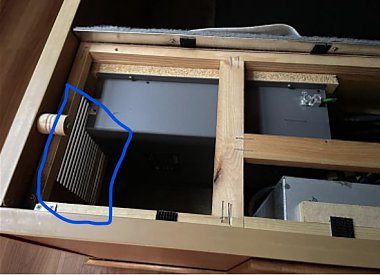
I think I can do better than that. I have an acquaintance on a discord server that has a 2005 Journey with the 2KW inverter. I think he showed me a picture of it being mounted under the bed. I just sent him a direct message and asked him to re-share that photo and one of his inverter sub panel. When/if he sends this I will post for others to see.
Now there is the issue with heat and being mounted under the bed, I will save that discussion for another day LOL.
__________________
2007 Winnebago Journey 36SG and 2013 Honda CRV Toad
e-Trailer XHD Towbar (Demco) Blue Ox baseplate, SMI Stay N Play brakes
|
|
|
|
|
04-21-2023, 05:35 PM
|
#15
|
|
Winnebago Master
Join Date: Nov 2018
Location: Pflugerville/Austin, Tx
Posts: 7,524
|
I see the option with the larger inverter to have been out from under the bed and the inverter itself not at the same location as the brekaer panel.
I think of the electronics as the heat while the breakeris less prone to over heat.
Maybe it is in compartment on the outside underneath? But since this style is not so handy to turn and look, I may be missing the location? 
[ATTACH] 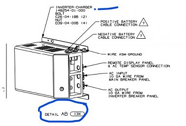 [/ATTACH]
__________________
Richard
Why no RV year, make and floorplan on MY signature as we suggest for others?
I currently DO NOT have one!
|
|
|
|
|
04-21-2023, 06:55 PM
|
#16
|
|
Just Trying to Help
Join Date: Aug 2015
Posts: 526
|
I erred in post #13; I should have said:
"I believe that the picture there shows an Eaton TT120FLGNM (flush mount) subpanel for the inverter."
__________________
Mark
2008 Holiday Rambler Admiral 30PDD (Ford F-53 chassis)
2009 Honda Fit Sport
|
|
|
|
|
04-21-2023, 07:03 PM
|
#17
|
|
Winnebago Master
Join Date: Nov 2014
Posts: 578
|
My buddy came through with a lot of pictures which I will share. As I said his is a 2005 Journey, and Wbgo mounted the 2KW inverter under the bed, with the sub panel to the right of the main panel as you pointed out.
I don't think I have that nice separation wall between the electrical space and the storage space, but I will be able to look tomorrow when I bring the Journey to the house.
The location you show in your last post for the inverter is where my existing 600W inverter is located. I have been planning for a 3KW to replace everything with but since my 600W still works well, I am wondering if I should just plan to add a 2KW inverter charger, and I could try it out under the bed to see if it gets too hot, or the fan makes too much noise for sleeping. It is all a fluid thing in my mind.
__________________
2007 Winnebago Journey 36SG and 2013 Honda CRV Toad
e-Trailer XHD Towbar (Demco) Blue Ox baseplate, SMI Stay N Play brakes
|
|
|
|
|
04-22-2023, 01:56 PM
|
#18
|
|
Winnebago Master
Join Date: Nov 2014
Posts: 578
|
I checked things out with an ohm meter. There are two busses and they alternate, 1, 3, 5, 7 are on one side and 2, 4, 6, 8, are on the other, Yes there are two live spaces under the blanks on my panel.
__________________
2007 Winnebago Journey 36SG and 2013 Honda CRV Toad
e-Trailer XHD Towbar (Demco) Blue Ox baseplate, SMI Stay N Play brakes
|
|
|
|
|
04-22-2023, 03:17 PM
|
#19
|
|
Winnebago Master
Join Date: Apr 2018
Location: Tucson, AZ
Posts: 1,215
|
Quote:
Originally Posted by tim myers
I checked things out with an ohm meter. There are two busses and they alternate, 1, 3, 5, 7 are on one side and 2, 4, 6, 8, are on the other, Yes there are two live spaces under the blanks on my panel.
|
Nice, you have an 8/16 BR series MLO that looks to be residential. Curious to know if there is any type of retainer or hold down device on the quad? Also I'm sure you are aware and probably wouldn't work it live anyway but the 2 main lugs on the right are hot anytime the panel is energized.
__________________
Brian
2011 Winnebago Via 25Q on 2010 Sprinter Chassis
|
|
|
|
|
04-22-2023, 03:22 PM
|
#20
|
|
Winnebago Master
Join Date: Nov 2018
Location: Pflugerville/Austin, Tx
Posts: 7,524
|
I notice a small detail that might still be something to think about is the small vent next to his inverter?
Is that a feature of the 36sg and not on your RV? Is that a vent letting cold air under the bed? Huumm??
__________________
Richard
Why no RV year, make and floorplan on MY signature as we suggest for others?
I currently DO NOT have one!
|
|
|
|
|
|
|
Currently Active Users Viewing This Thread: 1 (0 members and 1 guests)
|
|
|
 Posting Rules
|
You may not post new threads
You may not post replies
You may not post attachments
You may not edit your posts
HTML code is Off
|
|
|
|
 » Recent Discussions
 |
|
|
|
|
|
|
|
|
|
|
|
|
|
|
|
|
|
|
|
|
|
|
|
|
|


 Linear Mode

