 |
|
 04-03-2023, 10:37 AM
|
#1
|
|
Winnebago Camper
Join Date: Apr 2023
Posts: 22
|
House/coach battery question 2015 Era 70A
2015 Winnie Era 70A Question
We would like to install solar and lithium batteries. The MPPT charge controller has a place to wire in the alternator so it can control the charge via the solar panels or the alternator.
How would we incorporate this into the upgrade since it seems the alternator charges the chassis battery, which then goes to the solenoid and charges the coach(house)? Is the solenoid energized when the engine is turned on? Not clear how the solenoid for the Era is wired in as the schematics are 100% clear to me.
TIA
|

|

|
|
04-03-2023, 11:24 AM
|
#2
|
|
Site Team
Join Date: Sep 2009
Location: Spring Branch, TX
Posts: 7,818
|
I've never heard of such a thing.
As for wiring I would guess and it's just a guess that you'll pick up the wiring at the BIM or latching solenoid. I'd think a Sprinter based Era would have this. That way, the alternator is sending full charge to the chassis battery and then when the solenoid connects to the house battery that would go through your unique charge controller. But this is JUST A GUESS.
__________________
2017 Winnebago Adventurer 37F
2016 Lincoln MKX Toad
|
|
|
|
|
04-03-2023, 11:32 AM
|
#3
|
|
Winnebago Master
Join Date: Nov 2018
Location: Pflugerville/Austin, Tx
Posts: 7,499
|
That's one of the common things to know that seems difficult but easy to explain!
What to do is still something for you to decide but I can explain how it is wired and works as built.
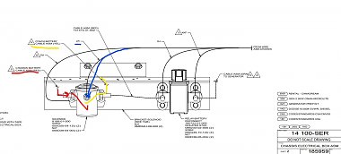
This is a snip of the drawings here:
https://www.winnebago.com/Files/File...ire_185959.pdf
Click this to get a better view or go direct to get the bigger story!
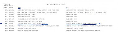
Winnebago uses a code for different wires and cables. The battery cables use this code to ID them.
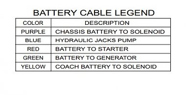
This is tape wrapped on the cables ends when new. However as they age it tends to drop off or get changed with new cables.
Small wires are ID'd with this code stamped on the wires.
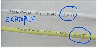
The stamped codes can be "decoded" here:
https://www.winnebago.com/Files/File...ical_guide.pdf
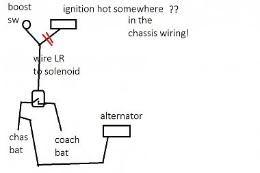
Your drawing has a small control wire from the dash that they call LR that brings the signal down to the coil in the solenoid, through the coil to the metal case which is grounded using a mounting screw on the RV body. I marked this wire in blue but it should have the ID stamped on it.
When this 12volt signal gets to the solenoid, the contacts close the two big lugs together.
Chassis battery may be marked with red tape and coach with yellow tape as marked here.
Wire LR is powered when we have the ignition on OR when we are pushing a switch on the dash sometimes called boost or AUX.
To keep the two from connecting when we drive, we can take either big cable off, insulate it and lay it back.
Or we can take the small LR wire off to keep the solenoid from working. No signal no work!
But if one wants to keep the use of the solenoid when we want to boost or "jump" a weak battery, there is one way we can cut off use but still use it in dead battery situations!
This is a very small current on the LR wire, so one way to have the cake and eat it too, is to cut the LR wire and install any type small switch in an out of the way place so it doesn't get flipped EXCEPT when you want to jump start the engine!
Keep the switch off most of the time but if you want/need a jump start, flip the switch on, push the dash switch to start and then be certain to flip the switch off before running long enough to overheat the alternator!
Choices , choices?? 
Small correction?
Your RV also has a second small wire FM which also brings ground to the solenoid as well as the mounting screw.
__________________
Richard
Why no RV year, make and floorplan on MY signature as we suggest for others?
I currently DO NOT have one! 
|
|
|
|
|
04-04-2023, 07:27 PM
|
#4
|
|
Winnebago Camper
Join Date: Apr 2023
Posts: 22
|
The solenoid engages either:
1 when the Battery Boost button (which is powered by coach batteries) is pushed and energized to solenoid, thus using the coach batteries to assist the chassis battery, or
2 the engine starts and a signal wire carry's the current from (black box / fuse box) to the solenoid thus allowing the chassis battery to charge the house battery via alternator.
So I understand this, and it makes sense, there really 'isn't' an alternator wire I can run to the MPPT charger. I would need to run this if I wanted to do that functionality. Also I would need to determine which wire is from the chassis 'black box' to disconnect so the solenoid ONLY engages when the Battery Boost is pushed.
So. Now the question is how to run the wire from the MPPT to attach to the alternator and is it worth it in the grand scheme of things.
|
|
|
|
|
04-04-2023, 07:42 PM
|
#5
|
|
Winnebago Master
Join Date: Nov 2018
Location: Pflugerville/Austin, Tx
Posts: 7,499
|
This is where I should admit that I have no experience with the parts you are talking about adding!
Best to admit I DON"T know rather than giving you bad advise!!
Several others here will have more experience with the solar and changing battery type!
__________________
Richard
Why no RV year, make and floorplan on MY signature as we suggest for others?
I currently DO NOT have one!
|
|
|
|
|
04-04-2023, 08:21 PM
|
#6
|
|
Winnebago Camper
Join Date: Apr 2023
Posts: 22
|
And thank you for the super helpful post!
Quote:
Originally Posted by Morich

That's one of the common things to know that seems difficult but easy to explain!
What to do is still something for you to decide but I can explain how it is wired and works as built.
This is a snip of the drawings here:
https://www.winnebago.com/Files/File...ire_185959.pdf
Click this to get a better view or go direct to get the bigger story!
Attachment 185531
Winnebago uses a code for different wires and cables. The battery cables use this code to ID them.
Attachment 185532
This is tape wrapped on the cables ends when new. However as they age it tends to drop off or get changed with new cables.
Small wires are ID'd with this code stamped on the wires.
Attachment 185533
The stamped codes can be "decoded" here:
https://www.winnebago.com/Files/File...ical_guide.pdf
Your drawing has a small control wire from the dash that they call LR that brings the signal down to the coil in the solenoid, through the coil to the metal case which is grounded using a mounting screw on the RV body. I marked this wire in blue but it should have the ID stamped on it.
When this 12volt signal gets to the solenoid, the contacts close the two big lugs together.
Chassis battery may be marked with red tape and coach with yellow tape as marked here.
Wire LR is powered when we have the ignition on OR when we are pushing a switch on the dash sometimes called boost or AUX.
To keep the two from connecting when we drive, we can take either big cable off, insulate it and lay it back.
Or we can take the small LR wire off to keep the solenoid from working. No signal no work!
But if one wants to keep the use of the solenoid when we want to boost or "jump" a weak battery, there is one way we can cut off use but still use it in dead battery situations!
This is a very small current on the LR wire, so one way to have the cake and eat it too, is to cut the LR wire and install any type small switch in an out of the way place so it doesn't get flipped EXCEPT when you want to jump start the engine!
Keep the switch off most of the time but if you want/need a jump start, flip the switch on, push the dash switch to start and then be certain to flip the switch off before running long enough to overheat the alternator!
Choices , choices??
Small correction?
Your RV also has a second small wire FM which also brings ground to the solenoid as well as the mounting screw. |
|
|
|
|
|
04-05-2023, 03:26 AM
|
#7
|
|
Winnebago Camper
Join Date: Apr 2023
Posts: 22
|
I use the term black box when I don't know where a wire is coming from since it seems to come from something possibly Mercedes did. Or leads to something Mercedes did like a fuse box or bus bar.
Last question:
Along with wire LR is another wire that is black. Could this be the wire from the black box? It has no label and I think it comes in from the same area (or at least the same tubing) as the chassis battery.
I hope the photo attached.
|
|
|
|
|
04-05-2023, 09:01 AM
|
#8
|
|
Winnebago Master
Join Date: Nov 2018
Location: Pflugerville/Austin, Tx
Posts: 7,499
|
Black box is as good as I know!
The problem we get is that Winnebago gives us info that we can use but then we get into the chassis and they are slow to turn loose of their stuff!
So what I know on the LR lead is that it seems to have two connections. One is the boost switch and then there is a bit of mystery where they tie the LR lead into a spot they call ignition hot on some chassis. Likely different brands use different names and I have never seen any drawings of where that spot is. Black box somewhere!
That's where I developed the idea that we might use a small switch as a way to make sure they did not operate the mode solenoid UNTIL we turn the switch on as a "Manual" way to allow a jump start.
But this is the first time. I've actually seen the wiring on an RV as you have it.
I did a little playing so we could look at what the drawwing shwos and what you really have. Some looks correct but some that is not shown!
Click for better view!
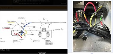
The big battery cables and marking look right and as shown on drawings.
Then when we get to the smaller. I think I see A small white wire at far left that I would expect to be FM going to the mounting but I can't see for sure?
Then a small second white wire near that and appears to go on with the chassis battery? Unknown what that does!
Possible aftermarket item ? Maybe added light, tire monitor, "SOMETHING?"
I would hope to find a fuse holder in that line?
One the center post, a small yellow that I would thing is LR, but no info on the black wire(??) but it looks kind of like it might match the black wire at the far right which is also a mystery!
OR the small black wire may be a number 8 which is shown as KKF and I know this is an area where we get confusion about turning the battery disconnect off and still having drains connected to run the battery down!
If this cblack wirre is labeled KKF,it goes to fuses/breakers that ARE disconnected when we flip the disconnect switch!
But the small yellow wire on the left side of this relay is wire GJ and that is left connected full time to feed safety items like CO and propane detectors!
Black wire power has to go through relay, while small yellow goes AROUND the relay to sneak up on us when we think we turned the power off!
So I think we can account for most of the wiring but possibly you have two that are not on the drawings as the left black wire and a small white wire on the battery supply at left?
Lots of ways to explain the white wire but what and why they are connecting anything to the control wirring LR from the dash or ignition hot? That is a big mystery. Maybe an added item they only want powered while the ignition is on? Back up lights or camera they added?
Automatic seat belt for a five year old? 
Do a bug hunt for anything that looks extra or maybe there is a loose wire that has just been cut off?
__________________
Richard
Why no RV year, make and floorplan on MY signature as we suggest for others?
I currently DO NOT have one!
|
|
|
|
|
04-05-2023, 09:15 AM
|
#9
|
|
Winnebago Camper
Join Date: Apr 2023
Posts: 22
|
Any idea how the chassis/alternator charges the house batteries? I am assuming somewhere in here the Chassis battery is charged by alternator, and when 'Full' charges the house batteries via the solenoid engaging.
From Winnebago: The house batteries will charge while driving or hooked up to shore power as long as the Coach Batteries are turned On. It seems the solenoid could possibly be energized when the van is started, but that doesn't account for the 'When the batteries are turned on' part.
|
|
|
|
|
04-05-2023, 10:56 AM
|
#10
|
|
Winnebago Master
Join Date: Nov 2018
Location: Pflugerville/Austin, Tx
Posts: 7,499
|
Yes, that sounds like it is correct but tends to give us the wrong idea!
Think of batteries as two buckets of water. When we connect the two buckets like with a pipe between them, the water tends to run from the full bucket to the empty bucket.
How fast that water runs depends on the difference in the two levels of water in the buckets.
So when we look at the definition of voltage, we find it is the difference in potential. Or we might call it the difference in power levels/voltages?
So if we connect a full battery to a half full one, the power tends to run from the high to the low. When we push the momentary dash switch (boost?) that makes the solenoid connect the chassis and coach batteries and we get the higher (more full?) coach batteries connected to the weak chassis battery and we can start the engine with more power just like we do if we pull a second car up and connect it with battery cables.
Then as the second thing the solenoid does is that when we have the key turned to ignition hot or engine running, the solenoid connects coach and chassis together. When we have the engine running the alternator on the engine is putting out power to charge the chassis as normal and that means higher voltage than either battery has.
Kind of like the two buckets connected together and we have a hose filling one?
It's a slow process but if we keep them connected and the alternator is filling them, both coach and chassis will eventually wind up at the same level!
Then when the alternator finds both batteries are "full", it backs off and tends to only put in as much as we take out, so lights, horn, and coach items like fans, lights, and pumps can all be used without running down any batteries. We can run down the road using all the power we want because we know the alternator is there to keep it all topped off!
Part of what we get into is the way drawings often show things. They often show the batteries as the alternator connected to the chassis battery and THEN connected to the coach and that gets us trapped into thinking the power has to go to the chassis battery first!
But the power works like water would! It doesn't care if the wire goes to one battery and then connects to another. It just goes to where the level is lower!
Maybe we should draw it more like the second picture and think of where water would run? 
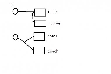
If the alternator is running and putting out 13-14 volts, some will run to the chassis battery if it is at 12 volts but far more will run to a coach battery if it is at 10 volts!
Hard to draw but if the alternator and batteries were setting on a shelf and water instead of power, the water will run to where the level is lower and stop when the levels are all the same as the alternator is putting out. We keep from overflowing things by letting the alternator back off when it reaches the set limit!
If we have a weak chassis battery and connect them, power runs from the coach if it is higher and that lets us start the engine. But once we start the engine both coach and chassis will get charged with the lower one getting more power than the other but at some point, both get full and the alternator backs off on what it is putting out to just maintain the set level.
It gets into a mindset thing at times. We tend to think if we turn on a fan in the coach, its comes from the coach battery but that battery is just a storage like a pantry. Does the power come from the storage or does it come from the alternator. Does an electron run out of the pantry to feed the fan or does a different one run from the alternator?
I'm not watching that close but just assume they will all get where we need them if we keep the path good and clean!
__________________
Richard
Why no RV year, make and floorplan on MY signature as we suggest for others?
I currently DO NOT have one!
|
|
|
|
|
04-05-2023, 11:06 AM
|
#11
|
|
Winnebago Camper
Join Date: Apr 2023
Posts: 22
|
I totally understand this. How does the solenoid get energized (while driving) to allow the flow of electricity from the chassis to the coach batteries, keeping in mind that, Per Winnebago, the Coach Battery switch must be ON which, in my mind, the Relay somehow comes into play and controls part of the flow.
|
|
|
|
|
04-05-2023, 11:11 AM
|
#12
|
|
Winnebago Master
Join Date: Nov 2018
Location: Pflugerville/Austin, Tx
Posts: 7,499
|
The part about the charging when the batteries are turned on is kind of confusing as it gets into how the shore power charges the coach batteries. The shore power runs a converter which is whaty we often call a battery charger! If we have the battery disconnect switch on, that converter/charger will charge the coach batteries.
But if we turn the battery disconnect off, the converter doesn't charge them!
Like the bucket idea? If we have it connected to shore power and converter is charging the coach batteries and then we start the engine, so that coverter, coach batteries and alternaotr and chassis batteries are ALL connected together, the power will tend to come more from which ever point is higher to the one which is lower but also some to any other point that is lower.
Like if we had all these items as buckets setting on a shelf and connected with pipes. power will flow from whatever is higher to where it is lower until they are all level, except I am sure they have something like a check valve to keep too much power from alternator from running into the solar, etc.
This is the "simple thinker" drawing!
__________________
Richard
Why no RV year, make and floorplan on MY signature as we suggest for others?
I currently DO NOT have one!
|
|
|
|
|
04-05-2023, 11:15 AM
|
#13
|
|
Winnebago Master
Join Date: Nov 2018
Location: Pflugerville/Austin, Tx
Posts: 7,499
|
Writing and drawing while you were posting!
Yes, the converter is only connected and charging the coach when the coach battery disconnect is closed/turned on!
__________________
Richard
Why no RV year, make and floorplan on MY signature as we suggest for others?
I currently DO NOT have one!
|
|
|
|
|
04-05-2023, 11:21 AM
|
#14
|
|
Winnebago Camper
Join Date: Apr 2023
Posts: 22
|
Now I am very confused since the alternator/chassis battery already are 12v. The only inverter/converter I see in the schematics is in use when the 110v is active (shore power). My understanding was:
All while the Coach Battery button is on:
When not running the 12v Coach would boost the chassis when the Battery Boost button is engaged energizing the solenoid (simple, easy)
When running, somehow the solenoid is energized that allows the chassis to charge the coach batteries (no need to convert it since its 12v)
My thought was once I determine what energizes the solenoid while driving, I can essentially disconnect/remove that wire. I would run a new 4/0 cable from the chassis battery to my MPPT controller where it specifically has a terminal for it. Then, no solenoid would be energized while driving, the alternator charge goes to the MPPT charge controller, and the battery boost would still work when engine is off since it's energized by pressing a toggle switch. That's why I am trying to determine how the solenoid is energized while driving and where that energy comes from.
Was editing for clarity while ya posted lol
|
|
|
|
|
04-05-2023, 02:29 PM
|
#15
|
|
Winnebago Master
Join Date: Nov 2018
Location: Pflugerville/Austin, Tx
Posts: 7,499
|
I think have most of that story right!
So the confusing part seems to be that wire LR as it gets power from two different places.
From the boost switch for jump starting but I am not sure if that is actually coach power or chassis battery. I'm guessing it has to be chassis power as I know the second way it gets power is from the ignition hot which is certain to be chassis.
That means they can't have a double connection, one coach one chassis without that making a full time connection between the two!
I have only seen this as explanation of where LR gets power, without mention of it also getting power from ignition hot!
From the wire ID list here:
https://www.winnebago.com/Files/File...ical_guide.pdf
If we look at the ID for LR, we get this:
LR comes from aux or boost switch ( different names different RV!) to the solenoid. Only by hunt and peck and reading other stuff did I find it gets power from ignition hot on the same wire but only when we have the key on! That end is considered part of the chassis and they hold that info tight if we are not part of the auto repair who can get manufactor info!
I know it is there and some call it ignition hot but where and how, I have never found!
Kind of like lots of things? I know it is there but I can't get much more than that! Part of that group that turns on the seat belt bell when you turn the key?
I think the charge from alternator to chassis battery will not be on wire LR but likely a bigger wire somewhere les, so if one were to find and cut the connection at the red slash marks, that would make sure coach and chassis would not connect through the solenoid when we turned the key on.
The problem being knowing where they did that and how to cut it off???
The only time I have any luck getting info on automotive wiring is some online forums or when the car gets so old nobody want the repair business any more! Then somebody writes a book like this:
https://haynes.com/en-us/ 
__________________
Richard
Why no RV year, make and floorplan on MY signature as we suggest for others?
I currently DO NOT have one!
|
|
|
|
|
04-06-2023, 09:27 AM
|
#16
|
|
Winnebago Camper
Join Date: Apr 2023
Posts: 22
|
Created a (very) simple diagram to make sure I had all things accounted for (as much as I could).
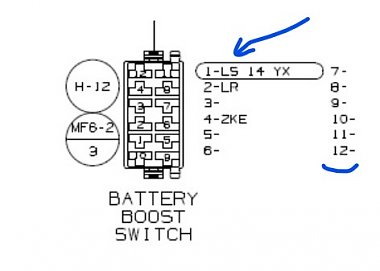
Engine off Power to energize Battery Disconnect Relay comes from Coach Batteries GJ to LJ, Coach Battery switch on, to LG closing the Relay Battery Disconnect. With relay closed, the Coach Battery power goes to the Battery Boost Switch KKF to LS. When Battery Boost switch is pushed, LS connects to LR and LR energizes the solenoid. This allows the Coach Batteries to connect to Chassis Battery via Red/Yellow, through energized solenoid, to the Red cable to the Chassis Battery, thus boosting.
Per Winnebago: When driving, if the Battery Coach switch is ON, the alternator/Chassis battery will slowly charge the house batteries. If the switch is off, the batteries will not charge.
Except for the unknown 2KE wire, I have no idea where the signal is coming from that energizes the solenoid while driving that allows the connection of the Chassis and Coach batteries. Additionally, I cannot see where/why/how the battery disconnect relay and/or switch factor into the charging while driving as I dont see any other incoming signals, other than possibly 2KE, which is past the relay disconnect.
KE: 14 YEL FROM: RUN ONLY POWER SOURCE TO: GENERAL PURPOSE (RELAY TRIGGER, REAR AUTO HTR,DRL,MONITOR,ETC
|
|
|
|
|
04-06-2023, 11:23 AM
|
#17
|
|
Winnebago Master
Join Date: Nov 2018
Location: Pflugerville/Austin, Tx
Posts: 7,499
|
I think that looks all correct as far as I know. Maybe some small points?
Is it possible/likely that the wire 2KE comes from the ingition hot or power when running point and actually meets the wire LR on the same lug, not going through any contacts, etc? That would let the solenoid get power when ignition on OR when we push boost switch??
How hard to get the boost switcvh so you could look on the back to verify that idea?
A funny wrinkle to confuse on on the battery disconnect is that it is an unusuale type called a latching relay. That means it has a magnetic sytem, so that it stays latched at the last posiiton evne when we let go of the disconnect switcfh as that switch is a momentary type. It only powers the relay when we are pushing it as the switch "bounces back" when we let go of it. That means we are not drawing power to hold the relay full time, saving battery. But the downside can confuse us because we can think we turned the switch on but if there was a battery problem, the relay statys where it was and may be left turned OFF when we thought we flipped the switch to ON!
We can finally chase down something not getting power to the relay, so it stays turned off and when we get a new battery or whatever solved, we still don't get lights to work because we have to go back and flip the switch again when it actually has power to move the relay!
I think you have it down pretty close to right with minor deetails like where the 2Ke and LR meet.
__________________
Richard
Why no RV year, make and floorplan on MY signature as we suggest for others?
I currently DO NOT have one!
|
|
|
|
|
04-06-2023, 02:31 PM
|
#18
|
|
Winnebago Camper
Join Date: Apr 2023
Posts: 22
|
I got an update from Winnebago: KE (or 2 KE) is not in their diagrams as it comes from the chassis. Gonna run some not so scientific experiments to check out my hypothesis.
And people question the scientific process lol.
|
|
|
|
|
04-06-2023, 03:11 PM
|
#19
|
|
Winnebago Camper
Join Date: Apr 2023
Posts: 22
|
Here is the scoop for anyone who's gonna go solar and wants to know about the battery boost/solenoid setup. Morich above, I and a few drawings from Winnebago led us to this:
The Coach Batteries are charged while driving via a wire (KE) that sends a low voltage to the solenoid via wire LR. This wire comes from 'somewhere' in the chassis to the Battery Boost. It's plugged into slot 4 of the Battery Boost Toggle. Slot 4 and 2 are NC (normally closed) leaving slot 1-2 NO (normally open).
When the van is turned on KE energizes the solenoid coil and thus allows the alternator to charge the coach batteries.
When the van is off KE has no current. When the van is on, KE is 12v
LS is from the coach battery and when the Battery Boost is pushed, it connects with LR and energized the solenoid coil, allowing the coach batteries to assist an ailing chassis battery.
Tests:
Toggle not pressed 2-4 NC, 1-2 NO, 1-4 nothing
Toggle pressed 2-4 is open, 1-2 is closed, 1-4 nothing
Measurements
Engine on
Toggle not pressed 2-4 NC (12v), 1-2 NO (nil), 1-4 nothing
Toggle pressed 2-4 open, 1-2 is closed (12v), 1-4 nothing (this isn't what you would normally do, just checking currents)
Engine OFF
Toggle not pressed 2-4 NC (no voltage), 1-2 NO (no voltage), 1-4 nothing
Toggle pressed 2-4 is open (no voltage), 1-2 is closed (12v), 1-4 nothing
To disable ALTERNATOR CHARGING this way, remove KE from Battery Boost and cap off and tape. Run your heavy gauge wire from the battery terminal to the Smart DC-DC MPPT charge controller where it will link up with the solar.
|
|
|
|
|
04-06-2023, 03:32 PM
|
#20
|
|
Winnebago Master
Join Date: Nov 2018
Location: Pflugerville/Austin, Tx
Posts: 7,499
|
Yes, I've found in blundering around that wires with numbers seem to be not a part of what they consider "their" wiring but connect to the chassis in some way. They are not found in the list I use but seem to go to things like a relay which is operated by chassis, etc.
Just as an interesting side point? We often think of builders as going as cheap as possible?
I had never dug into the boost switch and this is the first look at it and it makes me wonder!
It is a massive switch with potential to switch four wires, all in two different directions and that makes it something like a 4 pole, double throw?? and using 12 contacts in the switch but only wiring two contacts?
Seems there is a background story somewhere but it looks like they could have used a single pole, single throw to save a fair amount on the cost of switches??
Maybe they have lots of left over expensive switches to use up instead of the dollar priced type!
__________________
Richard
Why no RV year, make and floorplan on MY signature as we suggest for others?
I currently DO NOT have one!
|
|
|
|
|
|
|
Currently Active Users Viewing This Thread: 1 (0 members and 1 guests)
|
|
|
 Posting Rules
|
You may not post new threads
You may not post replies
You may not post attachments
You may not edit your posts
HTML code is Off
|
|
|
|
 » Recent Discussions
 |
|
|
|
|
|
|
|
|
|
|
|
|
|
|
|
|
|
|
|
|
|
|
|
|
|


 Linear Mode

