 |
|
 07-25-2022, 11:19 AM
|
#1
|
|
Winnebago Camper
Join Date: Aug 2020
Posts: 33
|
House battery relay
I have a 08 outlook 31c. I hit the switch at the door to turn on house batterys after storage and nothing
I took a reading of batteries with tester and they were dead
trickle charged them for 2days bringing them up to 12.8 v and hit switch
nothing.
I saw a lot of people had problems with that magnetic relay so I figured Id replace it as I could jump across poles and get house power
new one came today I put it in, have house power but cannot shut it off..maybe the on off rocket switch at door is bad? Is this a comon part to go bad? I dont know how to take any reading off switch back as there is like 8wires
Can anyone point me to ideas? Have you had the same problem? Thanks in advance for any help
good day!!!
|

|

|
|
07-25-2022, 03:04 PM
|
#2
|
|
Winnebago Master
Join Date: Nov 2018
Location: Pflugerville/Austin, Tx
Posts: 7,497
|
Yes, we should be able to point to a few things to help as you do fall into the right range to get the better wiring schematics on pre 2010 models.
Is this RV handy so that some testing can be done with reasonable time and effort? Or is it stored away from you?
Point being that we can cut the chase a bit by trying it and seeing what happens when the engine is running. The engine starting is very much like the normal car/truck making it less complex and more familiar than when we look at the whole RV.
But it also connects the start battery system and the engine alternator together with the coach 12VDC system. So if the relay and inside lights, vents, etc come alive, it can tell us a few things work and we don't need to look at those but can skip down a few lines in the chase!
So I kind of spend my day chasing things on electrical drawings and I've looked at the Winnebago set enough to feel comfortable with them. I will send along the link to them, so you have a choice of looking at them online or try to just use the snips of them I can post.
Different folks like different ways so you may want to get the complete picture or if that is not something you do much, the "snip" can be better!
You can often get a better look at these snips by clicking them if on a computer!
This is the drawing for your RV 12volt for the coach:
https://www.winnebago.com/Files/File...ire_162270.pdf
Page one is the part you need for the relay and has some important stuff to help understand what goes on in this critical area. For future maybe?
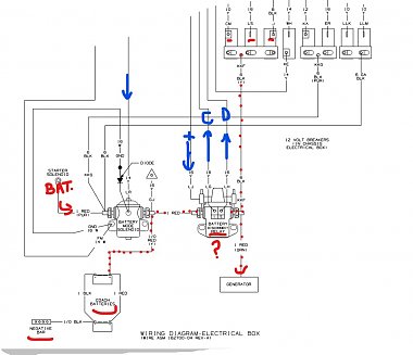
You have the right idea that there is a magnet gizmo on this as it is a latching relay. I've marked the control lines from the switch to the relay as easier to test at the relay then dig the switch out, perhaps? Or is it back out of reach on your RV?
There should be labels on the wire sides  as this example. We can "decode" the label here:
https://www.winnebago.com/Files/File...ical_guide.pdf
The positive battery comes in on a wire marked LJ and goes back to ground on either LG or LH to connect/engage (C?) or disconnect/disengage (D?).
So are you getting the 12VDC on the left side of the relay? They do a good job of making the drawinglook like what we actually see! If you get it there, does it get connected to the right side when you toggle the momentarty switch to turn on or off? Does the big red wire on left connect to the big red wire on right and onto all most all the coach ?
I marked the control wires from the switch to the realy in blue and you should find 12VDC on LJ going into the coil of the relay and meeting ground on either LG or LH, depending on which way you push the switch.
One way to test if you find the realy not working is to pull LG and lh off and see if the 12 volt is getting to the relay coil as well as getting thorugh at the posts where you pulled the wires off?? Dirty connections, open coil wire? That's where testing will help sort it.
But there is a good chance it is something less complex like dirty battery cables along the route and you may not find battery getting to the relay??
At the left is the mode solenoid which does the connection between the start battery and coach battery by using wire LR bring battery from the boost/aux switch when pushed or the ignition run circuit when the engine runs. This battery goes through the solenoid coil and down to ground on wire FM that is often on the mounting screw. This is a big one that can fail often as it does lots of arcing and really often (every time we start the engine).
See if that makes sense with what you find with a bit of looking and testing?
__________________
Richard
Why no RV year, make and floorplan on MY signature as we suggest for others?
I currently DO NOT have one! 
|
|
|
|
|
07-25-2022, 07:28 PM
|
#3
|
|
Winnebago Owner
Join Date: Sep 2011
Location: Denver, CO
Posts: 120
|
Just to supplement Richard's post, here is a schematic that shows how the "Salesman" switch on the wall reverses polarity to the latching solenoid. Hopefully you can enlarge by clicking on the pic.
Good luck with the fix.
__________________
Ed Sievers, Denver, CO
07 WBGO Outlook 31-C Sold Real good coach, just time to hang up the keys at 91.
"Be the person you needed when you were younger"
|
|
|
|
|
07-26-2022, 07:17 AM
|
#4
|
|
Winnebago Camper
Join Date: Aug 2020
Posts: 33
|
Thanks for the help! These schematics will help bigtime
yes coach is in yard and have access to it.
Also old switch wouldnt connect across (ie no house power on batteries) so I ordered and replaced it.once installing it and connecting batteries back house power automatically comes on and cannot be shutoff now (ie saleman switch wont turn it off and constant power is provided) I will try to do some test off of schematics and see what I can and get back to you guys, again thanks for your time
good day!
|
|
|
|
|
07-26-2022, 08:48 AM
|
#5
|
|
Winnebago Camper
Join Date: Aug 2020
Posts: 33
|
Heres a update, the positive wire your showing in schematic that goes to the 5amp fuse on top of magnetic relay shows nothing on multimeter and c and d in your drawing show nothing as well
but as stated power is going through new relay to power house off batteries
does this mean switch is shot?
|
|
|
|
|
07-26-2022, 09:56 AM
|
#6
|
|
Winnebago Master
Join Date: Nov 2018
Location: Pflugerville/Austin, Tx
Posts: 7,497
|
I may have mislead or confused the issue as I had the power coming from the wrong place on my drawing!
So let's make sure we are speaking the same thing?
Instead of the power coming down the wire shown from the switch, I should have had it going up ( if we can say which way the electrons run!) from the switch, as Dave73 has a much better drawing!
So are you saying there is no voltage on the left side of the relay where there is also a big red battery cable?
There should be a big red cable on the relay on the same connection as the small LJ wire and that short cable just goes to the mode solenoid post and meets another big red cable from the coach batteries.
If I'm reading right and you have no battery reading on the left of the relay, check the right side of the solenoid right beside it for voltage, if none there make sure the path is good from those cables all the way back to the coach batteries.
One point which may or may not be involved if that is the real problem is what they call "mega fuses" which can be in the line from the batteries to the mode solenoid.
On my Vista there was one on the frame directly behind the front right tire and it got almost all the water from the tire and was a real pain to keep clean!!
There should be battery on the big post on left side of relay---not the small wire. Big red cables almost straight from coach batteries!
Sorry if I confused things. Sometimes, I totally blow it! 
__________________
Richard
Why no RV year, make and floorplan on MY signature as we suggest for others?
I currently DO NOT have one!
|
|
|
|
|
07-26-2022, 08:47 PM
|
#7
|
|
Winnebago Owner
Join Date: Sep 2011
Location: Denver, CO
Posts: 120
|
Just another pic re the latching relay, Dave. As usual, click the pic to enlarge so you can read the wire markings. Your coach is 1 yr newer, but I really think they are the same in this area. I annotated this "after change out" pic yrs ago for another member. BTW- I changed out a perfectly good (operating) latching relay as a preemptive strike. I just kept reading about a lot of failures in the 10-15 year timeframe and didn't want to be bothered on the road. BTW-2: I changed out the boost solenoid next door to the latching relay at the same time. [I have been told I am a bit "wasteful" and am prone to "borrowing trouble". :^) ]
I have been reading forums for a long time now (weird pastime, but I enjoy learning from the many savvy folks that post here and on other forums as well.) Anyway, IIRC one RVer had a "salesman" switch problem a few years back. It's the only one I can recall reading about over the years ......... they don't fail (much).
You may have things all squared away by now...........hope so.
__________________
Ed Sievers, Denver, CO
07 WBGO Outlook 31-C Sold Real good coach, just time to hang up the keys at 91.
"Be the person you needed when you were younger"
|
|
|
|
|
07-27-2022, 06:46 AM
|
#8
|
|
Winnebago Master
Join Date: Nov 2018
Location: Pflugerville/Austin, Tx
Posts: 7,497
|
Thanks for posting that ED. I look at the drawings a lot and they make sense to me but there is never a time when a good pictures doesn't help to see how they match up with the drawings. 
I'm guessing that the real problem is not a failure of equipment but something simple like dirty and corrosion along the line.
__________________
Richard
Why no RV year, make and floorplan on MY signature as we suggest for others?
I currently DO NOT have one!
|
|
|
|
|
07-27-2022, 08:40 AM
|
#9
|
|
Winnebago Camper
Join Date: Aug 2020
Posts: 33
|
Here’s a update… the fused line to switch shows 12v at switch, when I read at the selinoid/relay for switching wires (LH&LG I believe they marked)it shows voltage but climbs slowly… 2.4v…4v..ect. Up to 12v, so lines are all working but relay isn’t clicking…could it be because the switch is gradually increasing volt that it doesn’t make it magnetize and switch it?
I ask because I took a battery and jumper cables touching to the two switching post and with a instant 12v the relay clicks…
So the switch is bad? Your thoughts
Again I can’t thank u guys enough for taking time outta your day for help!
|
|
|
|
|
07-27-2022, 10:45 AM
|
#10
|
|
Winnebago Owner
Join Date: Sep 2011
Location: Denver, CO
Posts: 120
|
Beginning too sound like dirty/poor electrical contact. I guess if it were mine, I would lift the coach battery ground and then pull that wall switch out from the wall (I "think" you can do that) and remove the wires, one at a time, clean the contact surface with contact cleaner and reassemble. I have had that switch pulled back on mine at one time, IIRC, but don't remember much about its physical properties. Reckon you could carefully read voltages in there with a meter, but I would be afraid of doing some unintentional welding. :^(
I'll be reading to see what Richard suggests, but his original thought re dirty/poor contact seems most logical at this point.
Hang in there ............ frustrating but surely fixable.
__________________
Ed Sievers, Denver, CO
07 WBGO Outlook 31-C Sold Real good coach, just time to hang up the keys at 91.
"Be the person you needed when you were younger"
|
|
|
|
|
07-27-2022, 11:03 AM
|
#11
|
|
Winnebago Master
Join Date: Nov 2018
Location: Pflugerville/Austin, Tx
Posts: 7,497
|
No problem! I need to keepmy mind from going to silly putty! Some days it works, some days not!
This switch is tricky but simple as it doesn't pass any currentor power when we are not prssing it in either direction. There is battery on some points and ground on others but no connection inside the switch to pass it on. That is done to save battery when we don't need to move the relay and it lets the magnet hold it where it last moved.
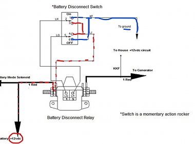
But if we push the switch one way it connects the battery and ground to two other points and lets it go to the relay.
So what this is doing when you push the switch one way, battery is put on the relay where it is labeled 1 on the drawing and ground on 2!
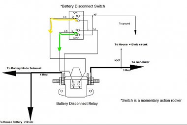
Then when you push the switch the other way, those 1 and 2 get reverersed battery and ground and that pulls the relay back the opposite direction!
But the tricky part is when we push that same switch the other way, the battery and ground going out is reversed, so that the relay moves the other direction!
First picture above?
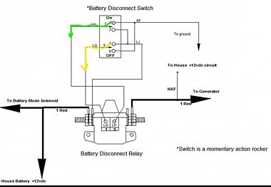
So if you look with a meter on the switch when it is not pushed, you should see no battery, no ground on pins 2 and 5 but they will show low resistance or a short between them as they are connected at the coil in the relay!
Those only get connected to other pins when we push the switch.
Looking at picture 2?
If you take the two small wires off at the relay, you should see battery one one of the wires when pushing the switch and then reverse battery and ground when pushing the switch the other way like in picture 3.
I don't see anything showing that would make the voltage change slowly but might expect the relay to jump right away as we don't need it to move slowly, just as long as it moves!
Can you hear or feel the relay jump each time you push first on and then off?
If the relay is something you can feel move, that is about all you need to study the switch but if it is mnoving and then not sending power on through to the right side, the relay points are not good.
__________________
Richard
Why no RV year, make and floorplan on MY signature as we suggest for others?
I currently DO NOT have one!
|
|
|
|
|
07-30-2022, 04:47 PM
|
#12
|
|
Winnebago Camper
Join Date: Aug 2020
Posts: 33
|
Ok I replace relay, switch and checked grounds and all wiring
any other reason this magnetic relay may not be shutting off? Im ready to delete it and just run a battery disconnect
anyone done that instead of the whole saleman switch mess?
|
|
|
|
|
07-30-2022, 06:11 PM
|
#13
|
|
Winnebago Master
Join Date: Nov 2018
Location: Pflugerville/Austin, Tx
Posts: 7,497
|
Well, that is a problem! If I read correctly, there really is no other item to go wrong with getting the realy tomove, so maybe let me question some things.
If you take the connections off the right side of the relay, you still see 12 volts on the relay lug swowing battery is connected through from left to right side? That means the relay contacts are closed and should pass power to alll the things in the RV.
That would mean the last time it worked it moved closed and the magnetis holding it that way. So what moves it the other way is when the battery and ground on LG and LH switch positions or polarity.
One way to test the new relay is to take the small wires off LG and LH and use a set of wires to put 12volt battery and ground directly on those points on the relay. IF the relay doesn't click or move, try switching the two wires to opposite of what you first tried and it should click as it moves the other way.
If the inside lights are on and won't go off, switching the two wires should make them go out!
Just be sure not to touch the two wires together and blow a fuse somewhere. But those two wires are like your hand moving a wall switch to turn lights on and off only instead of your hand the wires makes the relay move.
__________________
Richard
Why no RV year, make and floorplan on MY signature as we suggest for others?
I currently DO NOT have one!
|
|
|
|
|
07-31-2022, 02:20 PM
|
#14
|
|
Winnebago Camper
Join Date: Aug 2020
Posts: 33
|
Ok I got this tracker down to the white ground going to the switch… I took a jumper wire from Negative Terminal on battery and put it to white ground on switch and Viola! Switch turned power on and off…so does anyone know where it ends up? I traced it as far as I could go or thought it went as it’s under my counter… just wondering if you guys with the scemetics knew.. thanks again!!
Or would running a new ground for that wire off switch be a problem?
|
|
|
|
|
07-31-2022, 03:42 PM
|
#15
|
|
Winnebago Master
Join Date: Nov 2018
Location: Pflugerville/Austin, Tx
Posts: 7,497
|
Ok! That will certainly kill it, so we need to IDthat wire. I think you are speaking of wire KF on the drawing and I looked at the wire IDchart and all it tells us is it goes from the switch to ground! Great big help as we already thought that true.
so some looking finds there is a big bar, likely copper and likely mounted to the frame at some point with lots of other ground wires on it.
This is a drawing of the wires on it but not found WHERE, so still looking for actual location.
One place these are often found is near the batteries, so may look around there and hope to get lucky? I will do a closer look at the other info to see if I can spot a bus bar.
IfYou find a bus bar, counting the wires may be a help but also look for labels on thw ires as this example and it may help tell if you are on the right bus bar and then which wire to check?
EDIT: I find there is a differenceif Ford or GM chassis? Difference is 6th wire from end or 7th from right end, so be aware ofwhich might be closer todcorrect!
I will do some checking and get back shortly.
__________________
Richard
Why no RV year, make and floorplan on MY signature as we suggest for others?
I currently DO NOT have one!
|
|
|
|
|
07-31-2022, 04:14 PM
|
#16
|
|
Winnebago Master
Join Date: Nov 2018
Location: Pflugerville/Austin, Tx
Posts: 7,497
|
Not found the buss bar for sure yet but there is one that looks to be right at the batteries, so maybe worth a look there?
But chasing wire KF leads me to a plug under the range! Plugs can be a spot for things to go open, so it might be worth checking for this plug--- if it is where you can spot it?
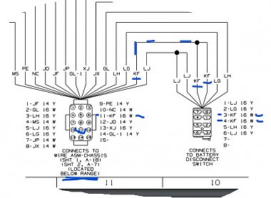
Looks like both pins 3 and 4 should have 16 gauge white wires on them at the switch and those go to combine and on tothe plug under the range where they show up as a single 16 gauge white wire on pin 11. From that point it shows they go straight to the ground bus.
That makes the question, which is it open at more likely, the buss bar or the plug?
In this case, I go to the one I find first and I'm comingup short on location of the bus bar but it looks likelots and lots of the RV coach items like water pump, lights, etc are all grounded to that one bar.
__________________
Richard
Why no RV year, make and floorplan on MY signature as we suggest for others?
I currently DO NOT have one!
|
|
|
|
|
07-31-2022, 04:56 PM
|
#17
|
|
Winnebago Owner
Join Date: Sep 2011
Location: Denver, CO
Posts: 120
|
Dave- I have plans to go over to my coach on Wed (wish it were sooner) and I will take a pic or two in the area where the 12vdc power comes to the fuse block there under the fridge. I have been in there quite a few times and I seem to recall there is both a (+) and (-) lug ......... but not for sure about that. Anyway, there certainly isn't a problem with running another wire to provide a ground for the salesman switch. If I am right, I "think" you will be able to run that new ground wire without drilling through the floor to get to the battery (or the battery's ground stud on the Ford frame.) There should be a way to get it behind the cabinets etc over to the area under the fridge. Just an option.
I'll get back to ya in any event.
Glad you hear you wrestled this one to the ground (no pun intended)  Gotta feel better about it.
Ed S.
__________________
Ed Sievers, Denver, CO
07 WBGO Outlook 31-C Sold Real good coach, just time to hang up the keys at 91.
"Be the person you needed when you were younger"
|
|
|
|
|
07-31-2022, 05:28 PM
|
#18
|
|
Winnebago Master
Join Date: Nov 2018
Location: Pflugerville/Austin, Tx
Posts: 7,497
|
Quote:
Originally Posted by youracman

Dave- I have plans to go over to my coach on Wed (wish it were sooner) and I will take a pic or two in the area where the 12vdc power comes to the fuse block there under the fridge. I have been in there quite a few times and I seem to recall there is both a (+) and (-) lug ......... but not for sure about that. Anyway, there certainly isn't a problem with running another wire to provide a ground for the salesman switch. If I am right, I "think" you will be able to run that new ground wire without drilling through the floor to get to the battery (or the battery's ground stud on the Ford frame.) There should be a way to get it behind the cabinets etc over to the area under the fridge. Just an option.
I'll get back to ya in any event.
Glad you hear you wrestled this one to the ground (no pun intended) Gotta feel better about it.
Ed S. |
If you can look around under there and possible spot a big copperbuss bar,that would be a major help as well. the problem with looking at drawings only withouthaveing the item to look at is the way we can see where it goes on the drawing but that is litttle help if we can't find it on the RV, so all help is needed~!
Since there are so many different circuits on that one bar, I might guess it would be bolted solid to the frame at some point and might be easy to spot but there are lots of spots on that frame and we can be looking right at the correct part but it can be on the other side!
They tell us so much but then when we look, it's like "everybody knows that" ! 
__________________
Richard
Why no RV year, make and floorplan on MY signature as we suggest for others?
I currently DO NOT have one!
|
|
|
|
|
08-01-2022, 05:01 PM
|
#19
|
|
Winnebago Owner
Join Date: Sep 2011
Location: Denver, CO
Posts: 120
|
Hi Guys- Thinking Dave's rig is laid out like my (1 yr older) 31-C, I did get over to take a few pics in the electrical panel area. On my coach the inside elec panel is below the fridge. The top left pic is an overview with the cover removed and with a speaker next door removed also. I "think" that when the PO of my rig had the converter upgraded to a Progressive Dynamics 55Amp unit it was maybe too big to fit in the space so the cabinet for it got tossed and the installer just installed the chassis? Anyway I put my small flashlight in the speaker hole area and opened the bottom cabinet drawer on its left....and I could see light...........so the pathway is open (sorta) over to the sink and the sink wall area where the salesman switch is. With the bottom cabinet drawers removed one could route a wire fairly easily. In the second pic there are the pwr wires (they come up from below) for the converter. I believe the two lugs on the right are + and the ground is on the left. (I shoulda put my meter on that.........I'll do that next visit.....probably Wed. In the last pic I show the left side of the converter and there is an air grille there with slotted holes. I would probably drill a hole next door to those slots and put a grommet in there for the new ground wire to pass through. Once into the converter, I could get up to the lugs shown above it easily enough. Probably not "best pracitce" but one should be able to add the (much smaller) stranded ground wire from the salesman switch to the wire in the appropriate lug there on the panel shown in the pic.
Lotta fish'in wire but I wouldn't want to be without the salesman switch .... even though I do have a manual battery ground disconnect switch on the coach batteries.
I shone the flashlight around in there a lot and could not see a sign of a nice ground bus bar .......... just crammed full of hoses, plumbing, a heat duct, etc. and of course the big cable bundle mentioned earlier. One has to wonder if the draftsman just used the bus bar template and there really isn't one.
Best. I'll get back if I am wrong on the polarity of those lugs in the pic.
__________________
Ed Sievers, Denver, CO
07 WBGO Outlook 31-C Sold Real good coach, just time to hang up the keys at 91.
"Be the person you needed when you were younger"
|
|
|
|
|
08-01-2022, 06:24 PM
|
#20
|
|
Winnebago Master
Join Date: Nov 2018
Location: Pflugerville/Austin, Tx
Posts: 7,497
|
There are almost always different ways to go about repairs but something to consider on this one is what happens next?
If they run a new ground wire to this point to get this item working, that sounds easy .
But if it is a problem with the ground buss bar getting loose or corroded so one circuit goes bad, what happens if the rest get corroded?
Since it is a big bar and it will be attached solidly (we hope) to the frame, I am inclined to bite the bullet now, rather than wonder when it will really jump up to hurt me!
But if only wanting to solve the problem for now, I would simply find a grounded piece of metal near the switch to run a wire to the switch.
One which is certain to give a good ground would seem to be close as the switch is at the door and the batteries are under a flap at that door with a major buss bar behind the batteries, so it would seem to be a pretty short stretch to get ground there. Or even go easier and tie it to the negative battery post!
But that is also assuming that bus bar is not the correct one to check the OEM wiring! There is a buss bar directly behind the batteries where they pick their ground.
__________________
Richard
Why no RV year, make and floorplan on MY signature as we suggest for others?
I currently DO NOT have one!
|
|
|
|
|
|
|
Currently Active Users Viewing This Thread: 1 (0 members and 1 guests)
|
|
|
 Posting Rules
|
You may not post new threads
You may not post replies
You may not post attachments
You may not edit your posts
HTML code is Off
|
|
|
|
 » Recent Discussions
 |
|
|
|
|
|
|
|
|
|
|
|
|
|
|
|
|
|
|
|
|
|
|
|
|
|


 Linear Mode

